Rotational direction switching clutch unit
a technology of rotating direction and clutch unit, which is applied in the direction of mechanical actuated clutches, interlocking clutches, transportation and packaging, etc., can solve the problems of complex structure and large number of components of the clutch unit, and achieve the effect of simplifying the structure, and reducing the number of parts
- Summary
- Abstract
- Description
- Claims
- Application Information
AI Technical Summary
Benefits of technology
Problems solved by technology
Method used
Image

Examples
embodiment 1
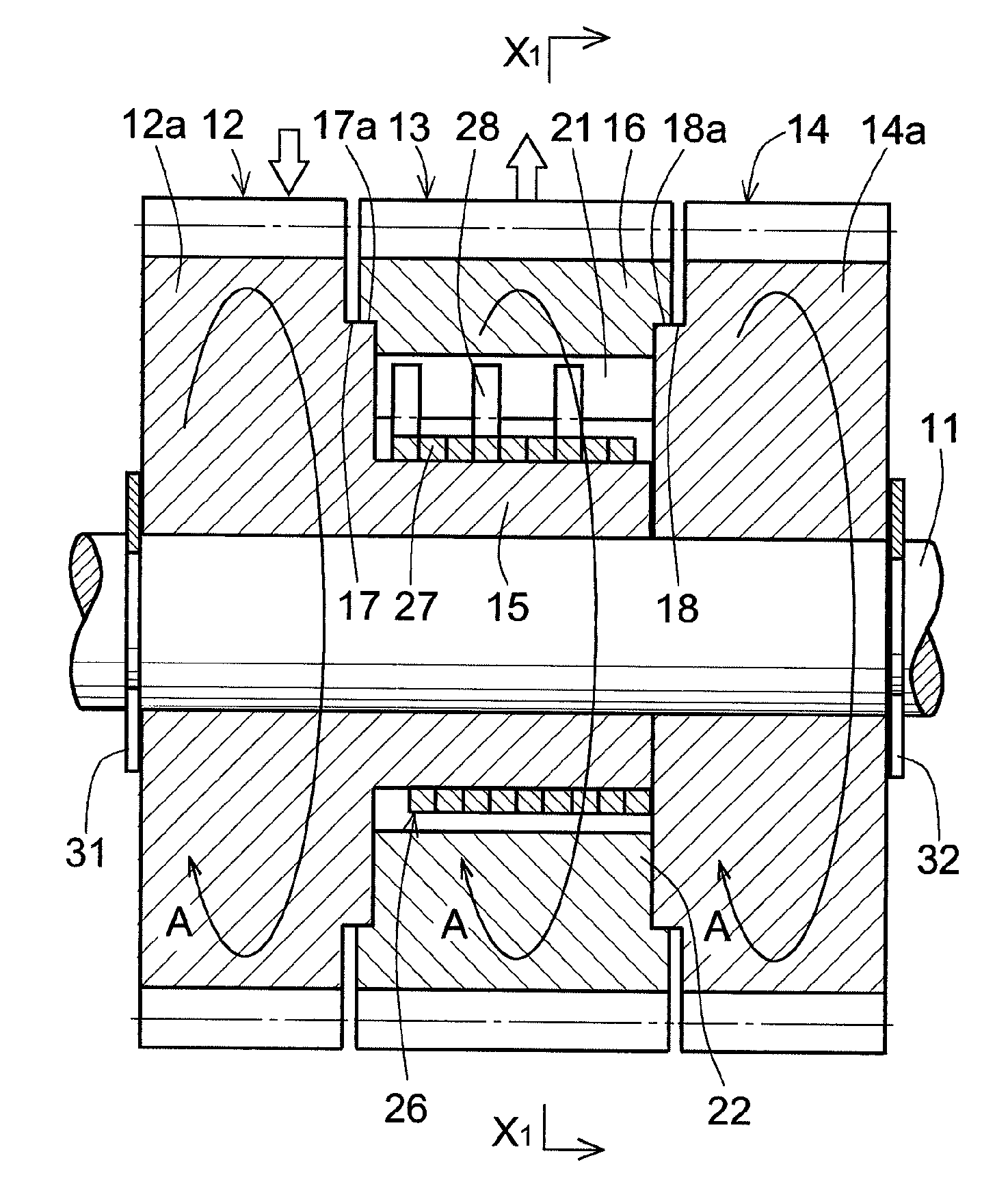
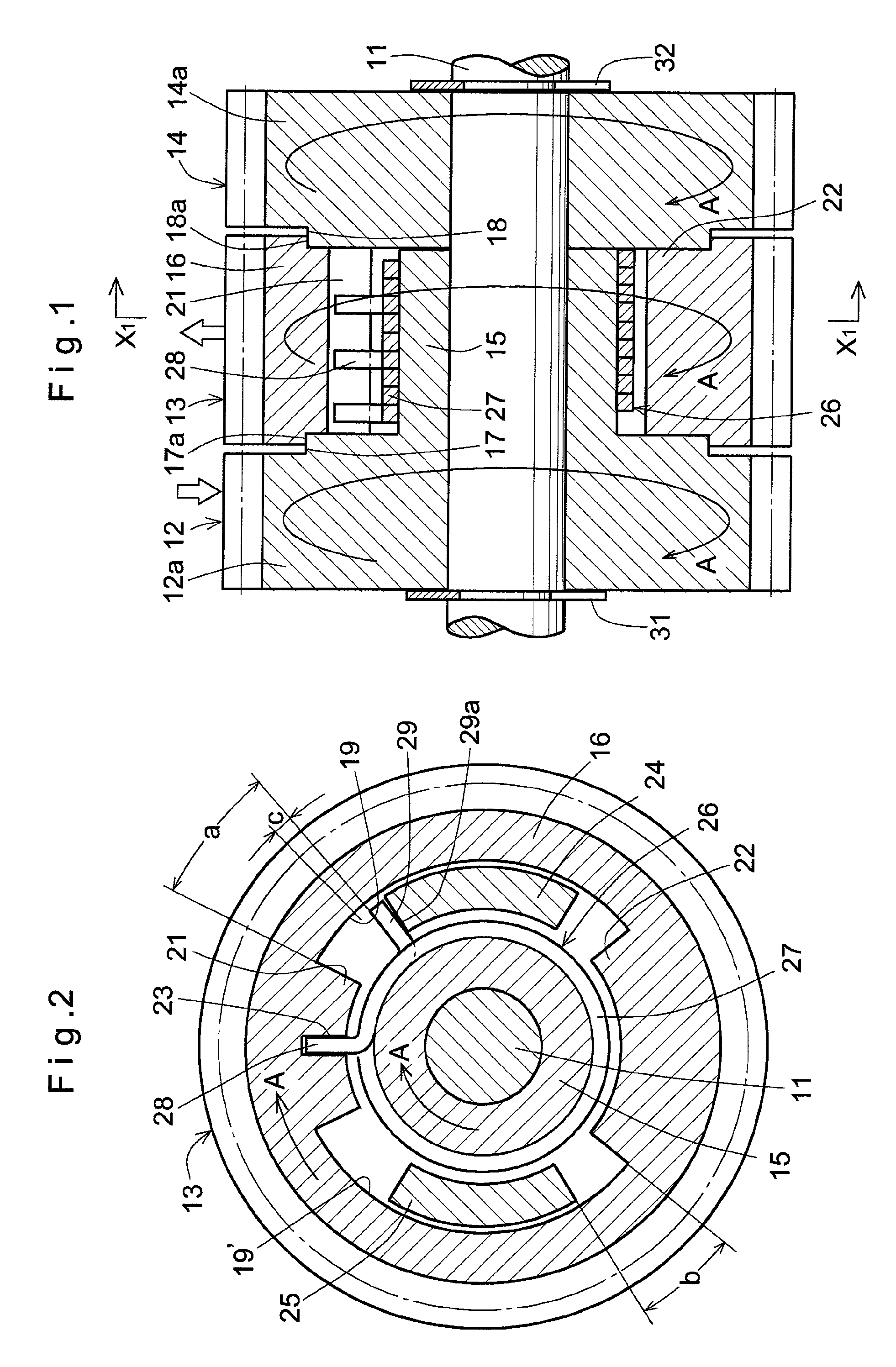
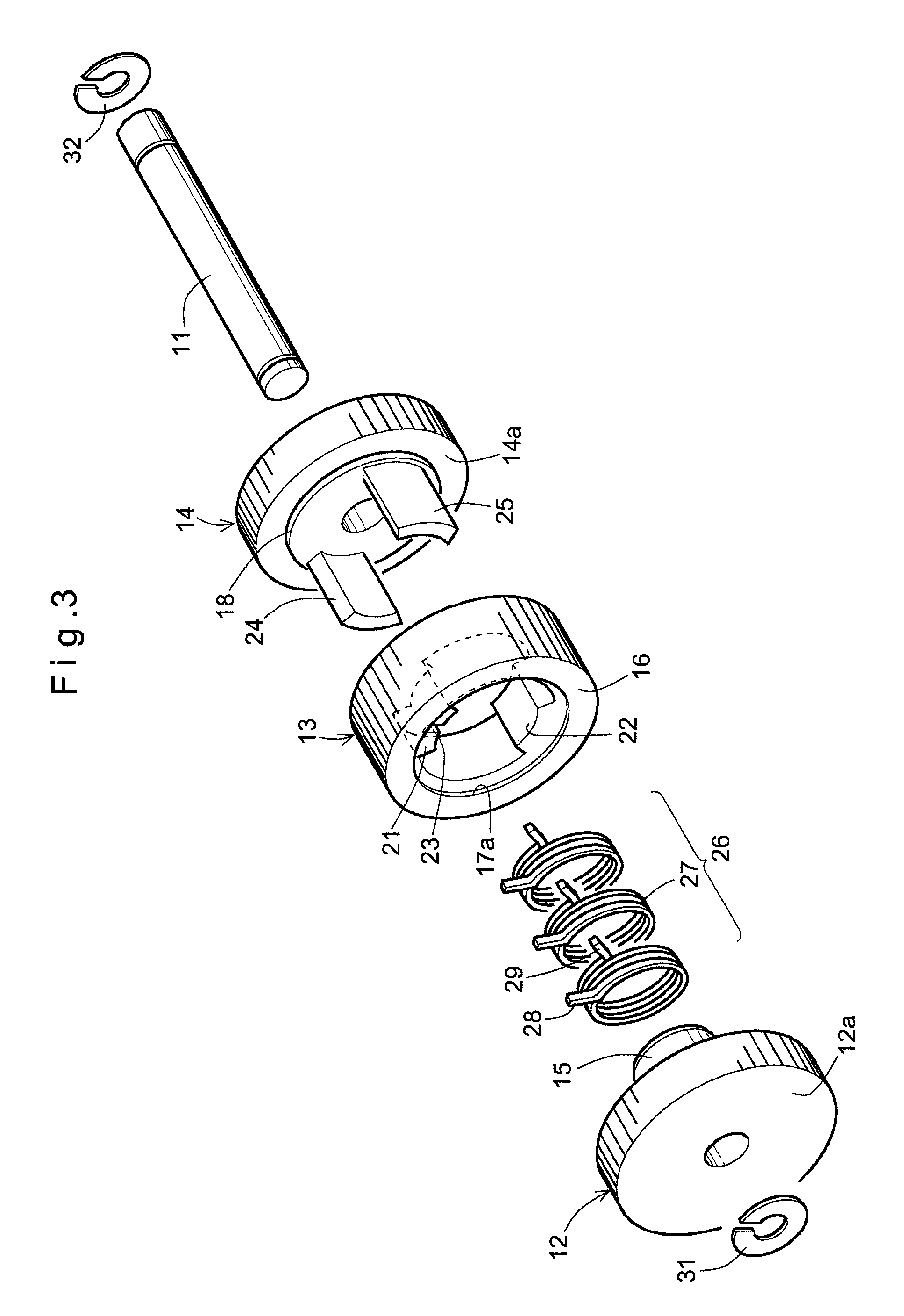
[0159]The rotational direction switching clutch unit according to Embodiment 1, shown in FIGS. 1 to 6, comprises an input gear 12, an output gear 13 and a reverse input gear 14 that are coaxially mounted on a fixed shaft 11 in this order.
[0160]The input gear 12 has an integral cylindrical input clutch portion 15 axially protruding from the center of the inner end surface of the gear body 12a. The input clutch portion 15 has its front end surface in abutment with the inner end surface of the reverse input gear 14. The input clutch portion 15 has a shoulder 17 on its radially outer portion. The reverse input gear 14 includes a gear body 14a having a shoulder 18 formed on its inner end surface so as to axially oppose the shoulder 17 and having the same diameter as the shoulder 17.
[0161]The output gear 13 is received between the opposed surfaces of the input gear 12 and the reverse input gear 14. Positioning steps 17a and 18a are formed on the respective end surfaces of the output gear ...
embodiment 2
[0185]FIGS. 7 to 11 show the rotational direction switching clutch unit of Embodiment 2, which differs from Embodiment 1 in that the reverse input gear 14, input gear 12 and output gear 13 are axially arranged in this order from left in FIG. 7, and are also slightly different in structure due to the difference in arrangement of these members.
[0186]In particular, the reverse input gear has at its central portion a boss portion 33 inserted in the input gear 12. A flange member 35 is coupled to the front end of the boss portion 33 through coupling portions 34 and 34′ comprising a protrusion and a recess. The flange member 35 comprises a flange boss portion 36 and a flange portion 37 is rotatably fitted on a fixed shaft 11. The boss portion 33 of the reverse input gear 14 and the flange boss portion 36 are coupled together through the coupling portions 34 and 34′ while axially abutting each other.
[0187]The boss portion 33 and the flange boss portion 36, which is coupled to the boss port...
embodiment 3
[0193]FIGS. 12 to 17 show the rotational direction switching clutch unit of Embodiment 3, which differs from Embodiments 1 and 2 in that the input gear 12, reverse input gear 14, and output gear 13 are axially arranged in this order from left in FIG. 12, and are also slightly different in structure due to the difference in arrangement of these members.
[0194]That is, the input gear 12 has a boss portion 38 comprising a large-diameter portion and a small-diameter portion 38′ with a shoulder defined therebetween. The boss portion 38 extends through the reverse input gear 14. A flange member 39 is coupled to the front end of the small-diameter boss portion 38′ through coupling portions 40 and 40′ comprising a protrusion and a recess. The flange member 39 comprises a flange boss portion 41 and a flange portion 42, and is rotatably mounted on the fixed shaft 11. The flange portion 42 is received in the output gear 13 at one end portion thereof. The output gear 13 is thus rotatably support...
PUM
 Abstract
Description
Claims
Application Information
 - R&D
- Intellectual Property
- Life Sciences
- Materials
- Tech Scout
- Unparalleled Data Quality
- Higher Quality Content
- 60% Fewer Hallucinations
Browse by: Latest US Patents, China's latest patents, Technical Efficacy Thesaurus, Application Domain, Technology Topic, Popular Technical Reports.
© 2025 PatSnap. All rights reserved.Legal|Privacy policy|Modern Slavery Act Transparency Statement|Sitemap|About US| Contact US: help@patsnap.com