Liquid and gas tight threaded tubular connection

Active Publication Date: 2012-10-16
VALLOUREC OIL & GAS FRANCE SAS +1
View PDF25 Cites 11 Cited by
  • Summary
  • Abstract
  • Description
  • Claims
  • Application Information

AI Technical Summary

Benefits of technology

[0014]The invention provides a connection of the type defined above in the introduction, and provides that a segment constituting at least a portion of the axial half-sections of each of the first and second axial abutment surfaces is incl

Problems solved by technology

If, in contrast, the thickness is lower, the lip is not sufficiently stiff and bends, possibly irreversibly, without transmitting the thrust to the sealing surface.
Thus, the prob

Method used


Image

  • Liquid and gas tight threaded tubular connection
  • Liquid and gas tight threaded tubular connection
  • Liquid and gas tight threaded tubular connection

Examples


Embodiment Construction

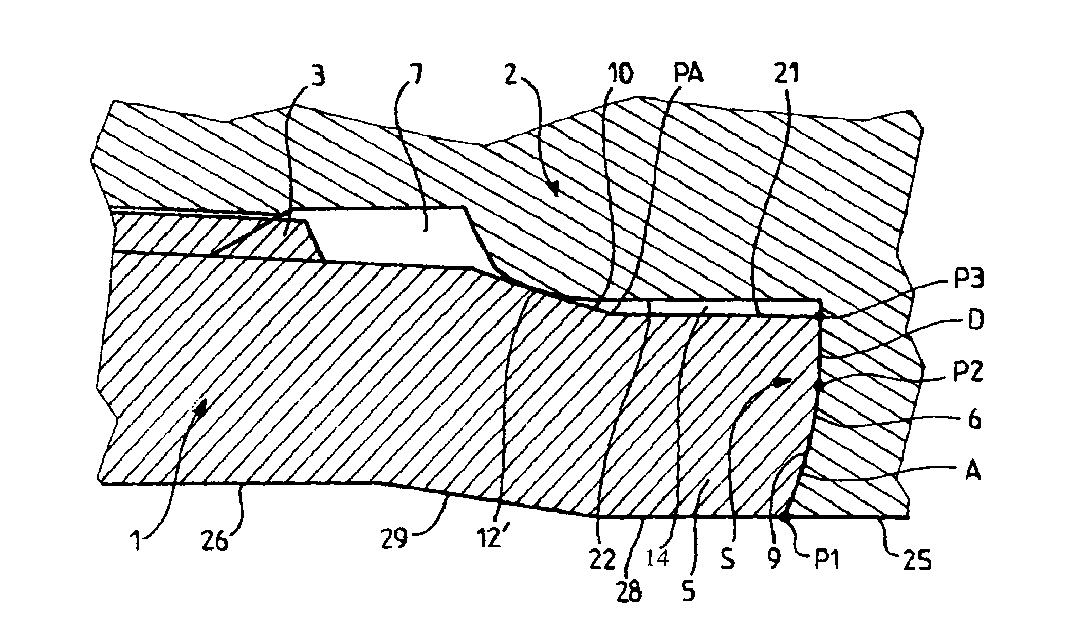
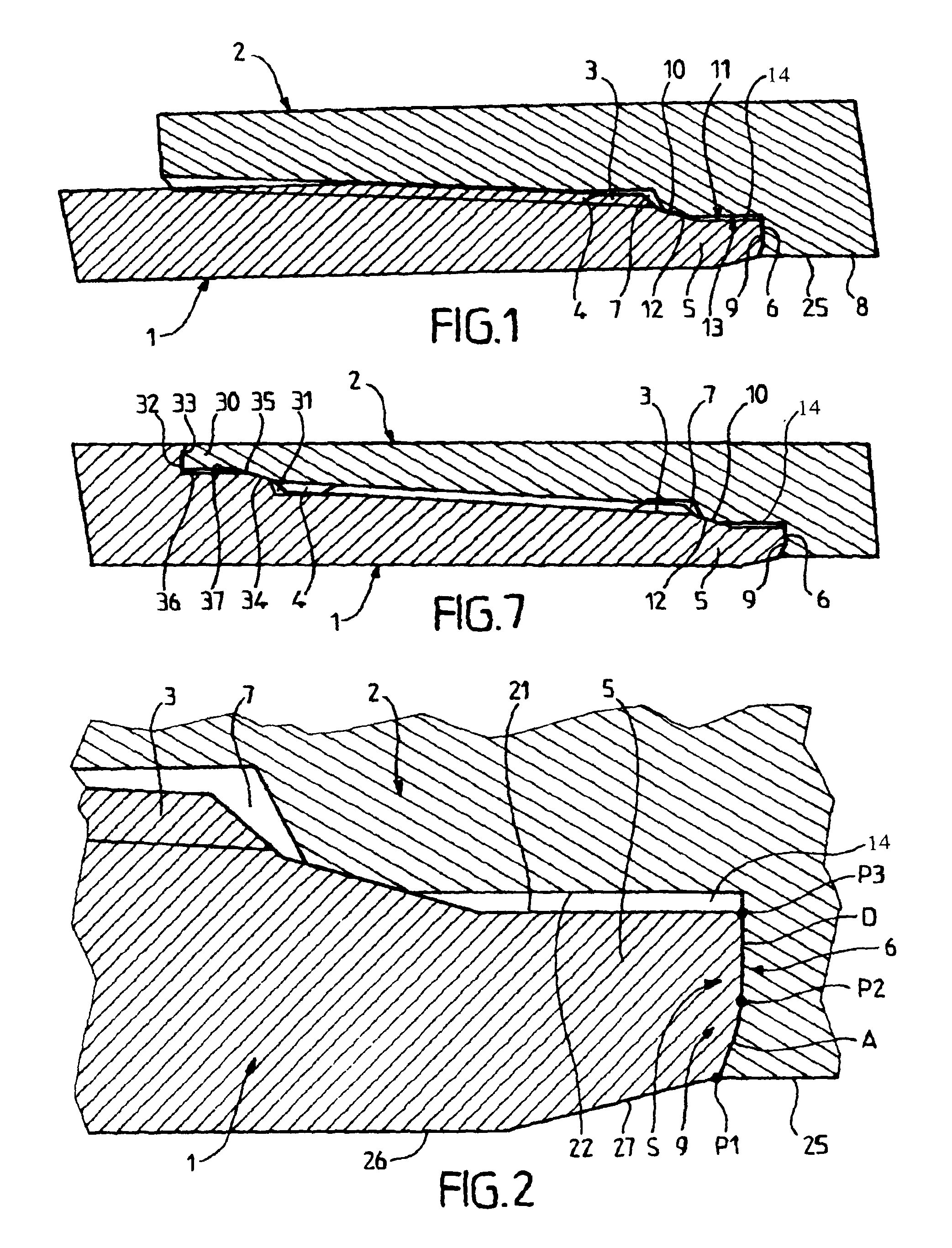
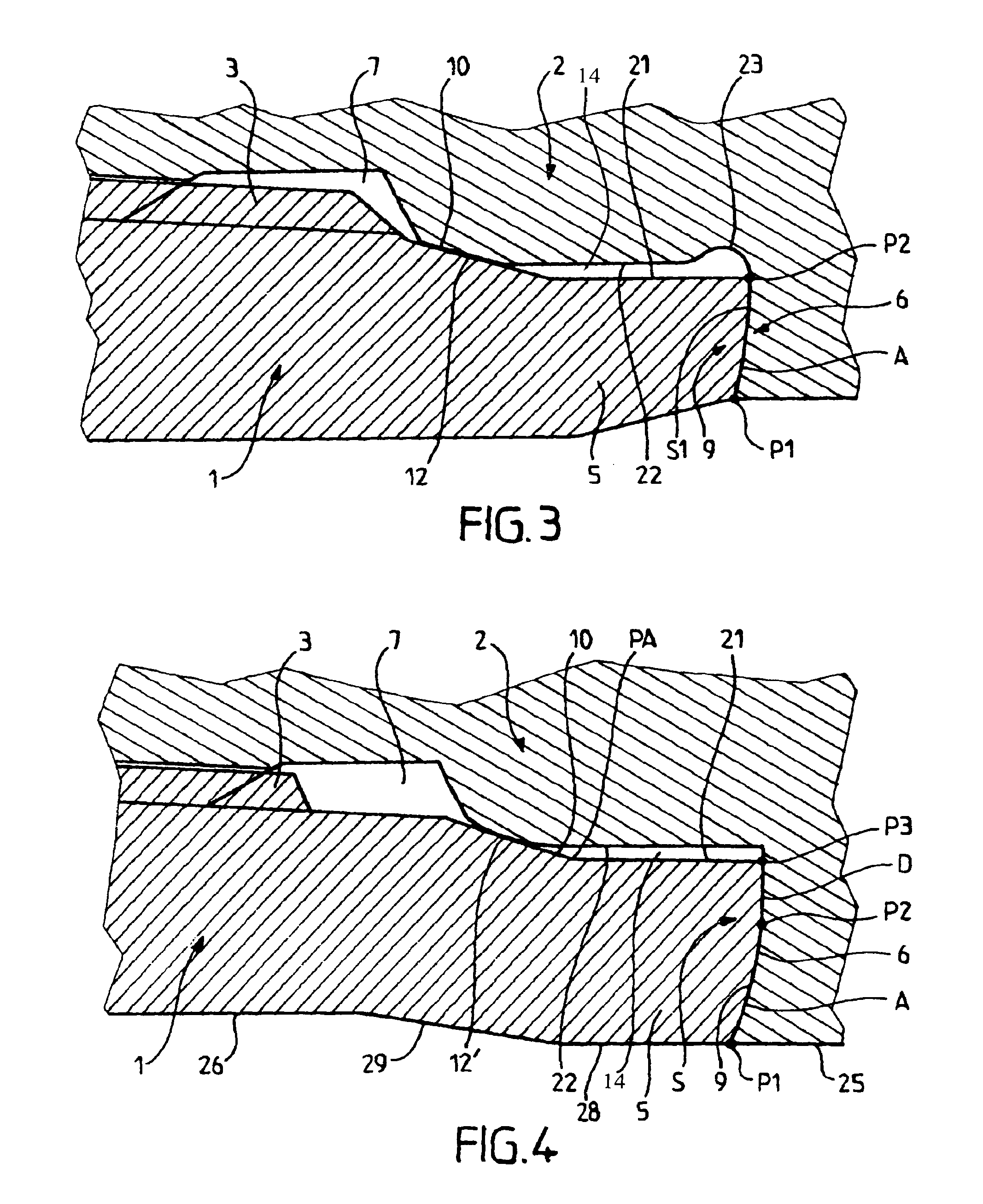
[0043]FIG. 1 shows part of a threaded tubular connection formed by a male tubular element 1 comprising a tapered male threading 3 and a female tubular element 2 comprising a tapered female threading 4. The male element 1 is formed at the end of a great length tube intended for forming part of a string of tubes in a hydrocarbon well, and the female element is formed either at the end of a further great length tube or at the end of a coupling provided at its other end with a further female element to connect two great length tubes together.

[0044]Beyond the threading 3, the male element 1 forms a male annular lip 5 ending in an end surface 6 which is approximately radial. A housing 7 following on from the threading 4 is formed in the female element 2 from its radially inner surfaces 8 and ends in an approximately radial end surface 9. A tapered annular sealing surface 10 is formed on the radially outer surface 11 of the lip 5 at a distance from the end surface 6, and a tapered annular ...


PUM


Abstract

A liquid and gas tight threaded tubular connection includes a first axial abutment surface formed at the free end of an annular lip of a threaded male element and a second axial abutment surface formed at the end of a housing of a threaded female element. The first and second axial abutment surfaces have the same axial half-sections, the inclination of which varies progressively in the radial direction.

Description

BACKGROUND OF THE INVENTION[0001]1. Field of the Invention[0002]The invention concerns a threaded tubular connection comprising a male tubular element comprising a male threading (thread profile) and a female tubular element comprising a female threading which can cooperate with the male threading on makeup, said male tubular element having a first annular axial abutment surface and a first annular sealing surface disposed on the radially outer surface of said male tubular element, said female tubular element having a second annular axial abutment surface and a second annular sealing surface disposed on the radially inner surface of said female tubular element, the first and second axial abutment surfaces coming into mutual abutment at the end of makeup while the first and second sealing surfaces come into sealing contact by radial interference, one of the first and second axial abutment surfaces, termed the distal abutment surface, being formed at the free end of a first of said tu...

Claims


Application Information

Patent Timeline
IPC IPC(8): F16L15/00
CPCF16L15/004E21B17/042
Inventor CHARVET-QUEMIN, JEAN-FRANCOISEMERY, JEAN-PIERREHAMAMOTO, TAKAHIROSUGINO, MASAAKI
Owner VALLOUREC OIL & GAS FRANCE SAS
Why Eureka
Try Eureka