
Stretched film and method for producing the same

a technology of stretched film and stout, which is applied in the field of stretched film, can solve the problems of deterioration of quality and disadvantageous wrinkles of polymer film, and achieve the effects of convenient adjustment of refractive index nx, convenient adjustment of nz coefficient, and setting up production equipmen

Active Publication Date: 2013-09-05
KANEKA CORP
View PDF23 Cites 10 Cited by
  • Summary
  • Abstract
  • Description
  • Claims
  • Application Information

AI Technical Summary

Benefits of technology

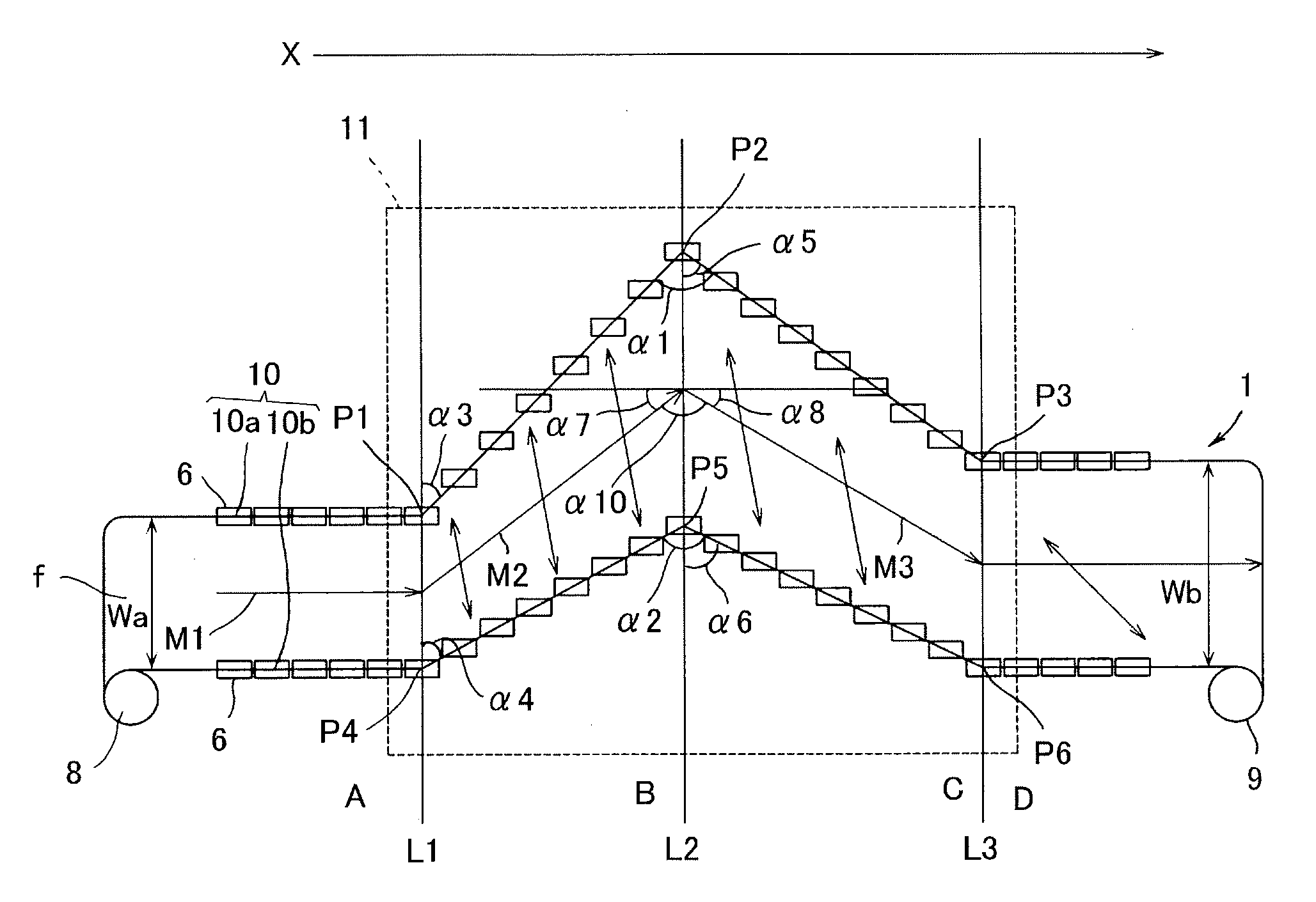
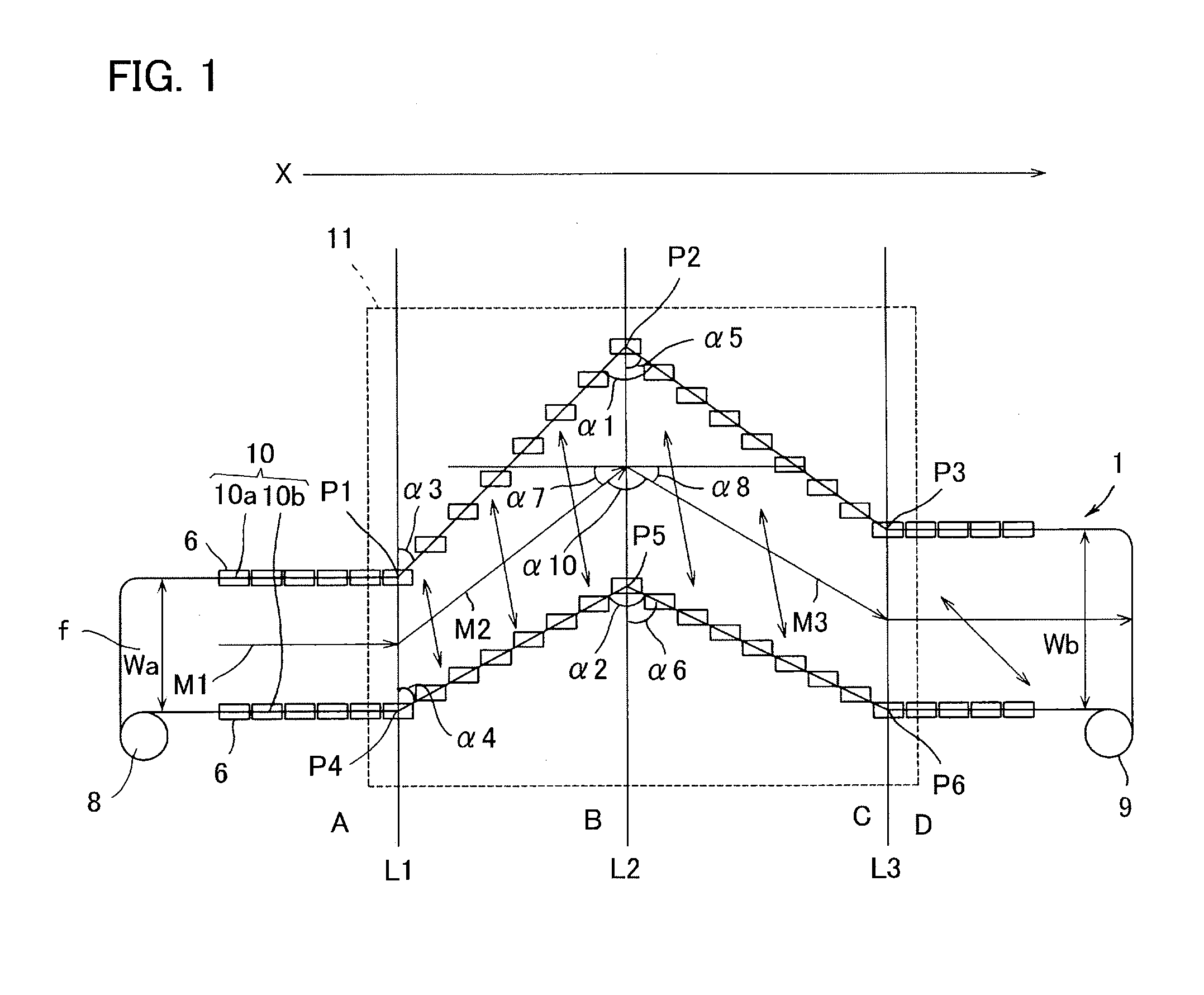
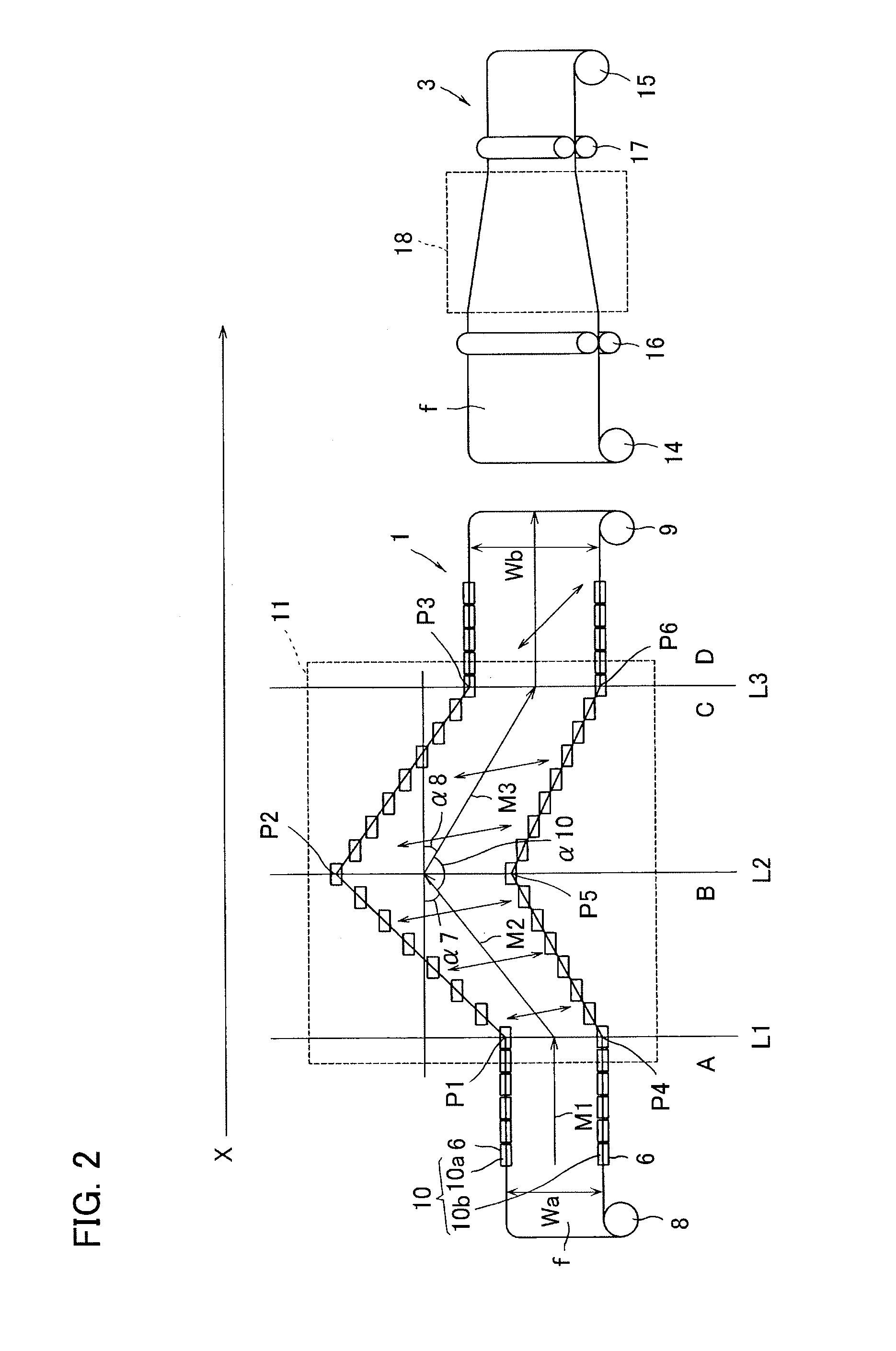
The present invention allows for a stretched film to be produced without a large difference in traveling distances between the film's edges, which means that production equipment can be set up in a small space. Additionally, the method facilitates adjusting the refractive index and the Nz coefficient within a desired range, which makes it easier to produce high-quality films.

Problems solved by technology

Stretching or relaxation heat treatment of a polymer film may disadvantageously wrinkle the polymer film.
Wrinkles of the polymer film may damage flatness of a retardation film to be formed, resulting in deterioration of quality.

Method used


Image

  • Stretched film and method for producing the same
  • Stretched film and method for producing the same
  • Stretched film and method for producing the same

Examples


example 4

[0260]A polycarbonate film (“ELMECH R-film unstretched” produced by Kaneka Corporation) was introduced into a stretching machine corresponding to the tenter stretching machine 1 in FIG. 2. A temporary stretched film was obtained according to Example 1 except that the film had an inclination angle of a center line (the area C center line inclination angle) at shrinkage at 0 degree. After each of the stretching and the shrinkage, the Re, the inclination angle of the orientation axis, the Nz coefficient, and the presence of wrinkles of the film were measured. The conditions are set forth in Table 1 and the results are set forth in Table 2. Herein, the temporary stretched film was not subject to the stretching in the longitudinal direction (the third step).

example 5

[0268]The present Example appropriately set values such as α (alpha) 3, α (alpha) 4, α (alpha) 5, α (alpha) 6, α (alpha) 7, α (alpha) 8 shown in FIG. 1, so as to produce various stretched films. The Re (retardation), the inclination angle (θ (theta) r) of the orientation axis, and the Nz coefficient of each of the stretched films were measured. As to a part thereof, a width of a required furnace was checked. The conditions such as the stretching and the shrinkage were according to the above-mentioned Examples 1 to 4.

[0269]Experiments were conducted with divided roughly into three conditions (Experiments 1 to 3).

[0270]In the following Experiments 1 to 3, a film stretched by the traveling trajectory disclosed in Patent Document 1 described above was a standard (Comparative Example). The traveling trajectory of this Comparative Example was shown in FIG. 13. This Comparative Example includes such the traveling trajectory that, in a first step, one side edge in a width direction of a lon...

example 1

of the Above-Mentioned Technique

[0411]A polycarbonate film (“ELMECH R-film unstretched” produced by Kaneka Corporation) was introduced into a stretching machine corresponding to the stretching machine 202 for preliminary stretching in FIG. 19, so as to obtain a polycarbonate film having a Re (retardation) of 570 nm measured at a wavelength of 590 nm, an orientation axis inclined at 6 degrees with respect to the width direction, a thickness of 40 μm, and a width of 1000 mm. The resulting polycarbonate film was introduced into a tenter stretching machine corresponding to the thermal shrinkage machine 203 for angle adjustment in FIG. 19. The film was heated at 160 degrees centigrade and equally decreased in width between the pinching members in the width direction, so as to undergo shrinkage by 40% (percent) in the width direction, and whereby a stretched film was obtained. Then, the retardation film inspection system RETS produced by Otsuka Electronics Co., Ltd. was used so as to meas...


PUM

PropertyMeasurementUnit
angleaaaaaaaaaa
angleaaaaaaaaaa
widthaaaaaaaaaa

Abstract

The present invention aims at providing a method for producing a stretched film, the method achieving suppression of wrinkles formed on the stretched film and limitation of biaxiality of the stretched film within a desired range and being carried out with simple facilities and providing a stretched film having optical properties suitably usable as a retardation plate.A first step of stretching a long film by increasing a holding distance in the width direction and a second step of shrinking the long film having been stretched in the first step by decreasing the holding distance in the width direction are performed. One side edge in the width direction of the long film travels with at least three bending travels, while the other side edge paired with the one side edge travels with at least two bending travels. Further, the first step or the second step performs the bending travel at one or both of the side edges in the width direction of the long film. Further, the first step or the second step has a traveling trajectory in which the both side edges in the width direction of the long film travel to the same side.

Description

TECHNICAL FIELD[0001]The present invention relates to a stretched film and a method for producing the same. The present invention relates particularly to a stretched film having a molecular orientation axis inclined with respect to one side of the film and being excellent in optical properties and to a method for producing said stretched film.BACKGROUND ART[0002]Recently, liquid crystal display devices represented by monitors (displays) for personal computers and television receivers are in widespread use as various display means. In these liquid crystal display devices, it is known that visibility of display is enhanced by technology such that a polarizer is arranged at each side of a liquid crystal cell and further a retardation film is provided between the liquid crystal cell and the polarizer.[0003]Herein, a retardation film is formed in a rectangle shape to fit on a liquid crystal display device. Such a retardation film for use in the liquid crystal display device may be requir...

Claims


Application Information

Patent Timeline
Patent Type & Authority Applications(United States)
IPC IPC(8): B29C55/02
CPCB29C55/045B29C55/02B29K2995/0018B29C55/04G02B5/30
Inventor YASUTOMO, NORIKAZU
Owner KANEKA CORP
Learn More