Magnetic head for perpendicular magnetic recording with shield around main magnetic pole

a perpendicular magnetic and magnetic recording technology, applied in the field of magnetic recording heads for perpendicular magnetic recording, can solve the problems of magnetic defect, unstable magnetic flux, and inability to produce magnetic defects, so as to prevent the generation of magnetic defects and facilitate the determination of the shape of the two side shields.

Active Publication Date: 2012-10-16
HEADWAY TECH INC
View PDF16 Cites 28 Cited by
  • Summary
  • Abstract
  • Description
  • Claims
  • Application Information

AI Technical Summary

Benefits of technology

[0020]It is a first object of the present invention to provide a manufacturing method for a magnetic head for perpendicular magnetic recording with a shield provided around a main magnetic pole, the manufacturing method being capable of preventing the generation of a magnetic defect in two side shields that the shield includes, and allowing the shapes of the two side shields to be determined easily.
[0021]It is a second object of the present invention to provide a magnetic head for perpendicular magnetic recording and a manufacturing method for the same, the magnetic head including a main magnetic pole that is capable of achieving both the prevention of adjacent track erase and the improvement of write characteristics, and a shield provided around the main magnetic pole, the magnetic head being capable of preventing the generation of a magnetic defect in two side shields that the shield includes, and allowing the shapes of the main magnetic pole and the two side shields to be determined easily.
[0022]It is a third object of the present invention to provide a magnetic head for perpendicular magnetic recording with a shield provided around a main magnetic pole and a manufacturing method for the same, the magnetic head being capable of preventing the generation of a magnetic defect in two side shields that the shield includes, allowing the shapes of the two side shields to be determined easily, and being capable of preventing leakage of magnetic flux from the main magnetic pole to the two side shields.

Problems solved by technology

The following problem arises with the first method if the two side shields are formed by plating.
The seam is therefore prone to be inferior in magnetic properties to other areas of each of the plating films, and thus can result in a magnetic defect.
In the area near of the position of the magnetic defect in each of the plating films or side shields, magnetic flux is unstable and the direction of magnetization tends to be pinned.
As a result, a large magnetic field can be generated locally in the side shields, which can result in the occurrence of adjacent track erase.
In the area of each of the plating films or side shields near the projection of the seed layer, magnetic flux is unstable and the direction of magnetization tends to be pinned, as with the magnetic defect caused by the seam.
Therefore, it may be said that the area of each of the plating films near the projection of the seed layer can also result in a magnetic defect.
The magnetic defect can locally generate a large magnetic field in the side shields, which can result in the occurrence of adjacent track erase.
Typically, patterning of a layer by using etching requires a larger number of process steps and more time than in the case of patterning of a layer by using only photolithography.
The first method therefore has the problem of high cost in manufacturing magnetic heads because of the need for a large number of process steps and much time to determine the shapes of the two side shields.
This means that the second method also requires a large number of process steps and much time to determine the shapes of the two side shields, and therefore has the problem of high cost in manufacturing magnetic heads.
On the other hand, the following problem arises if the main magnetic pole is shaped such that its end face located in the medium facing surface decreases in width with decreasing distance to the top surface of the substrate.
This results in degradation of write characteristics such as overwrite property.
If a magnetic head with a wrap-around shield and a main magnetic pole of the foregoing shape is to be formed by the conventional manufacturing method, a large number of process steps and much time are required to determine the shapes of the two side shields and the main magnetic pole.
This results in higher costs in manufacturing the magnetic head.

Method used


Image

  • Magnetic head for perpendicular magnetic recording with shield around main magnetic pole
  • Magnetic head for perpendicular magnetic recording with shield around main magnetic pole
  • Magnetic head for perpendicular magnetic recording with shield around main magnetic pole

Examples


Embodiment Construction

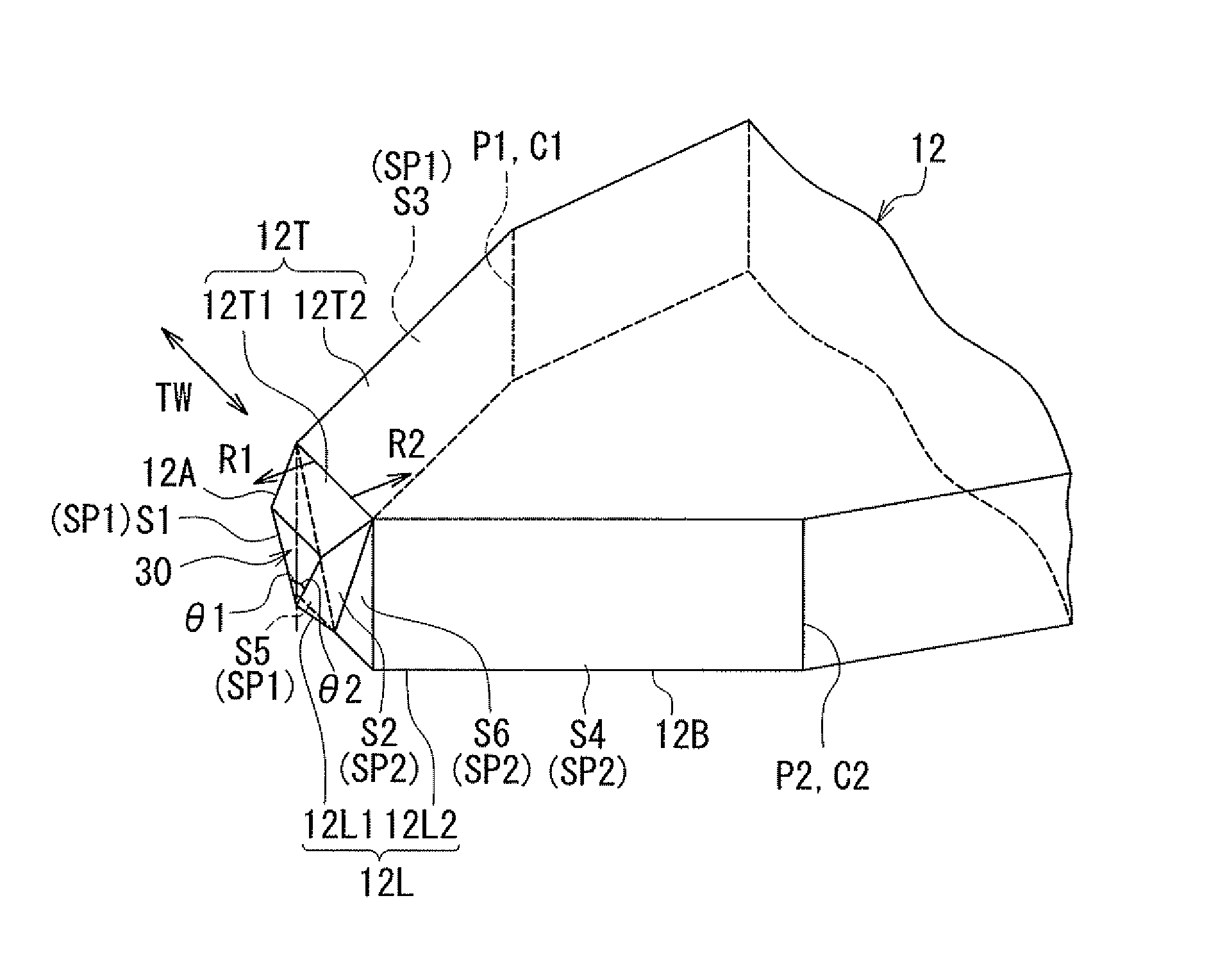
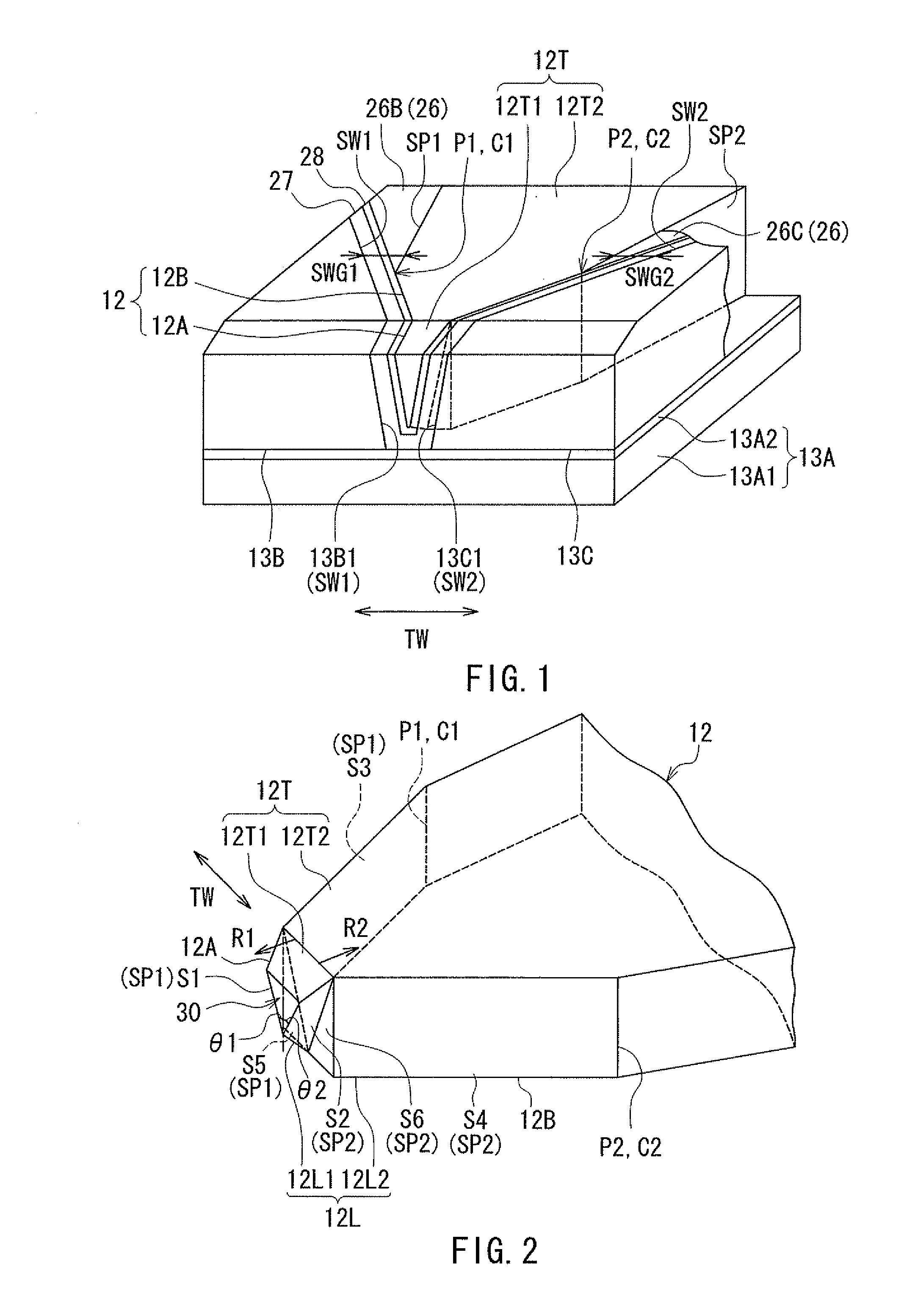
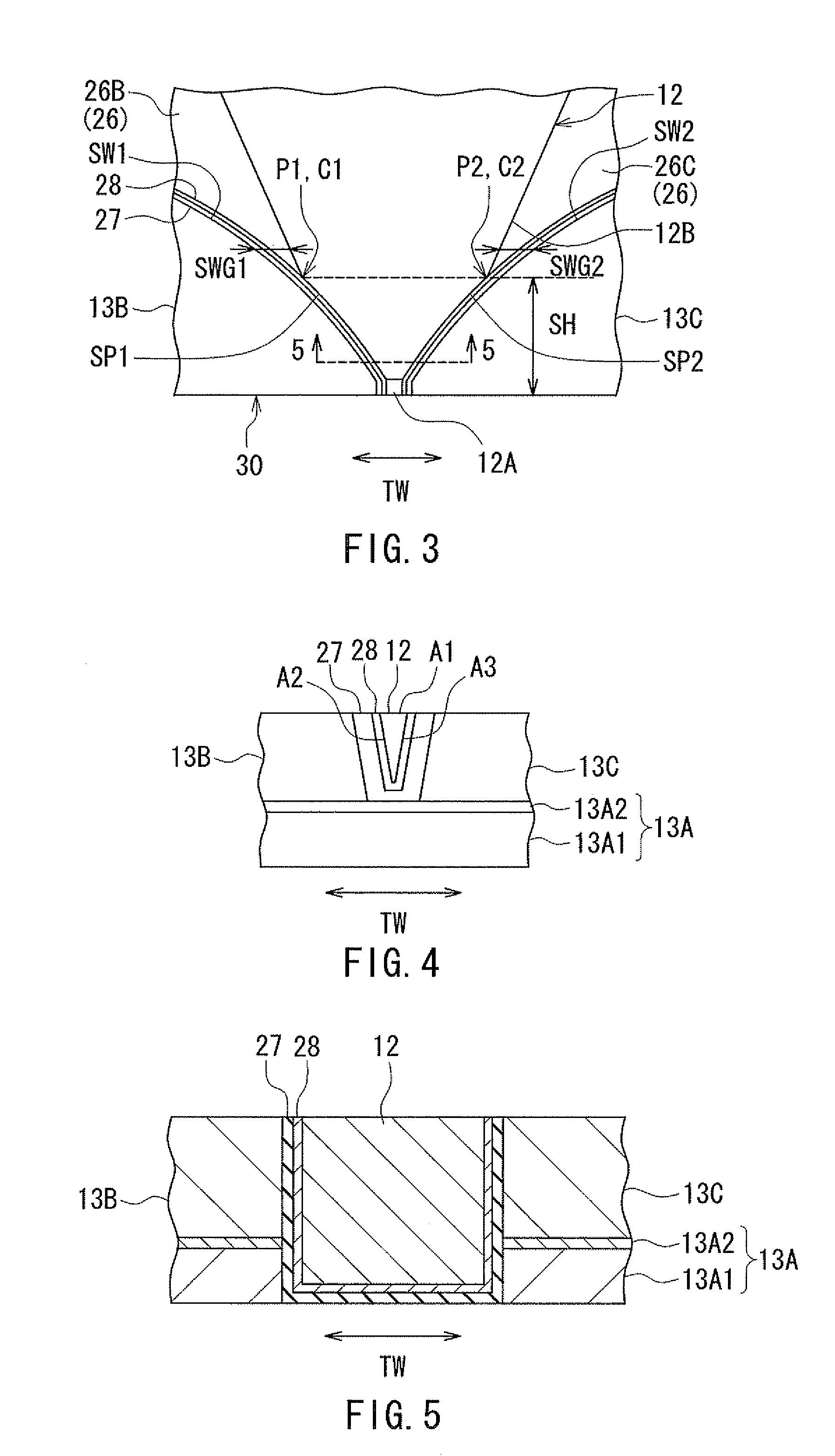
[0078]An embodiment of the present invention will now be described in detail with reference to the drawings. First, reference is made to FIG. 1 to FIG. 7 to describe the configuration of a magnetic head according to the embodiment of the invention. The magnetic head according to the embodiment is one for use in perpendicular magnetic recording. FIG. 1 is a perspective view of a main magnetic pole, two side shields, and a bottom shield of the magnetic head according to the embodiment in an area near the medium facing surface. FIG. 2 is a perspective view of the main magnetic pole of the embodiment in the area near the medium facing surface. FIG. 3 is a plan view of the main magnetic pole and the two side shields of the embodiment in the area near the medium facing surface. FIG. 4 is a front view showing respective end faces of the main magnetic pole and the two side shields located in the medium facing surface of the embodiment. FIG. 5 is a cross-sectional view showing cross sections...


PUM

PropertyMeasurementUnit
distanceaaaaaaaaaa
thicknessaaaaaaaaaa
thicknessaaaaaaaaaa

Abstract

A magnetic head includes a main magnetic pole, a shield having an end face located in a medium facing surface to wrap around an end face of the main magnetic pole, and a gap part provided between the main magnetic pole and the shield. The shield includes a bottom shield, two side shields, and a top shield. The gap part includes first and second gap layers. In a manufacturing method of the magnetic head, a mold is formed on the top surface of the bottom shield, the mold having a shape determined by photolithography and being intended to be removed later. Next, the two side shields are formed on the top surface of the bottom shield by performing plating without forming a seed layer. Next, the mold is removed and then the first gap layer, the main magnetic pole, the second gap layer, and the top shield are formed in succession.

Description

BACKGROUND OF THE INVENTION[0001]1. Field of the Invention[0002]The present invention relates to a magnetic head for perpendicular magnetic recording that is used for writing data on a recording medium by means of a perpendicular magnetic recording system, and more specifically, to a magnetic head for perpendicular magnetic recording that has a shield provided around a main magnetic pole, and a method of manufacturing the same.[0003]2. Description of the Related Art[0004]The recording systems of magnetic read / write apparatuses include a longitudinal magnetic recording system wherein signals are magnetized in a direction along the plane of the recording medium (the longitudinal direction) and a perpendicular magnetic recording system wherein signals are magnetized in a direction perpendicular to the plane of the recording medium. It is known that the perpendicular magnetic recording system is harder to be affected by thermal fluctuation of the recording medium and capable of providin...

Claims


Application Information

Patent Timeline
Patent Type & Authority Patents(United States)
IPC IPC(8): G11B5/127
CPCG11B5/1278G11B5/3116G11B5/3163G11B5/315Y10T29/49032
Inventor SASAKI, YOSHITAKASATO, KAZUKIITO, HIROYUKIHORINAKA, TAKEHIROYASUDA, KAZUMASA
Owner HEADWAY TECH INC
Why Eureka
Try Eureka