Dampened compression spring rod

a compression spring and rod body technology, applied in the field of compression spring rods, can solve the problems of premature failure, loss of control force, subsequent loss of spring life, etc., and achieve the effect of reducing the load and reducing the ra

Active Publication Date: 2012-10-23
BARNES GROUP
View PDF47 Cites 72 Cited by
  • Summary
  • Abstract
  • Description
  • Claims
  • Application Information

AI Technical Summary

Benefits of technology

[0007]The present invention provides an improved compression spring system which overcomes the above referred-to difficulties and others with regard to such rods heretofore available. The compression spring system in accordance with the invention is particularly adapted for lifting or pivoting one component relative to another component at a controlled rate. In accordance with one embodiment of the invention, the spring system provides a lift mechanism for hinged covers and the like that operates automatically upon release of the cover, and/or a lift mechanism for a loaded platform wherein the platform is elevated, progressively, as the load thereon is reduced. In accordance with still another and/or alternative embodiment of the invention, the spring system applies a s

Problems solved by technology

Consequently, because these products contain a gas and/or fluid, they are subject to premature failure, due to the leak

Method used


Image

  • Dampened compression spring rod
  • Dampened compression spring rod
  • Dampened compression spring rod

Examples


Embodiment Construction

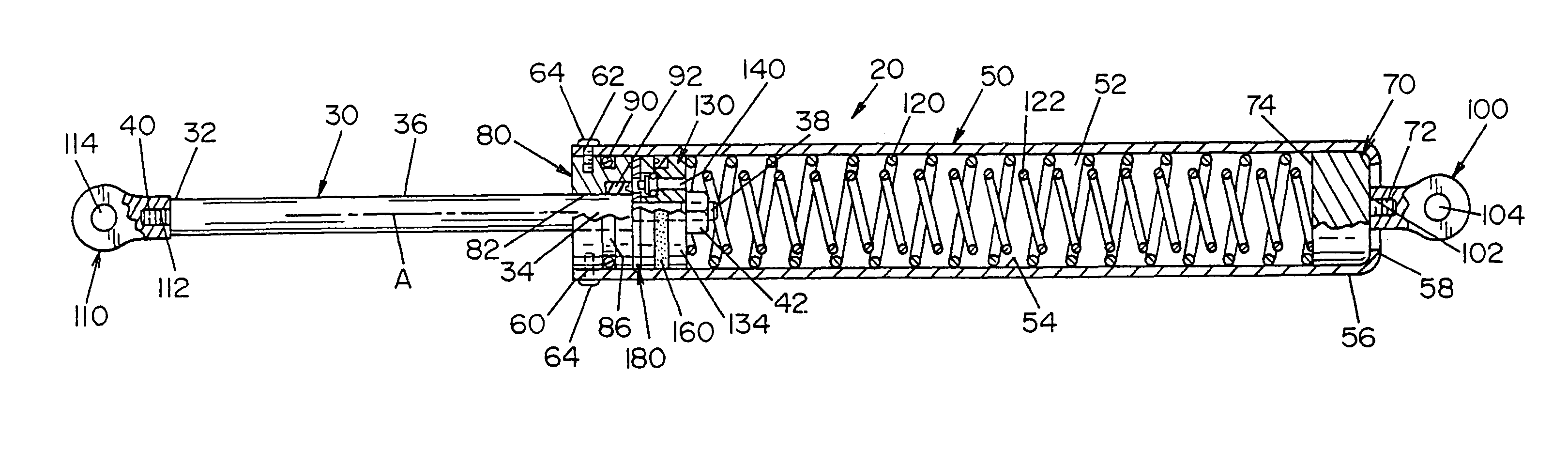
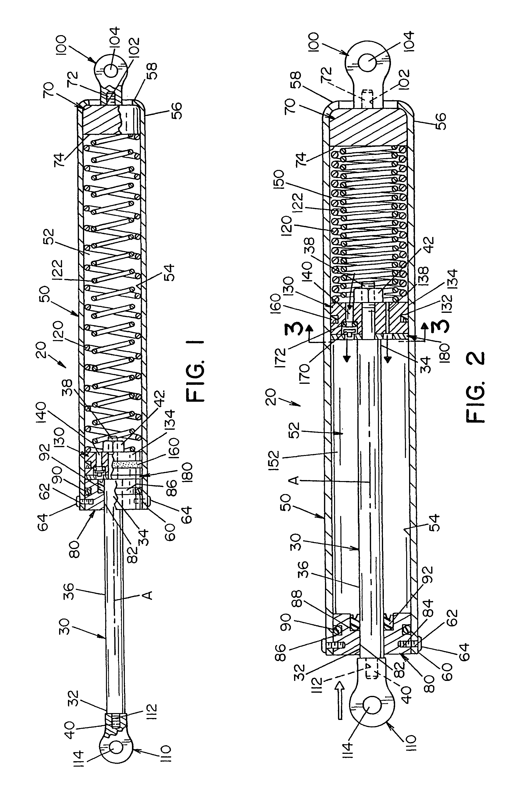
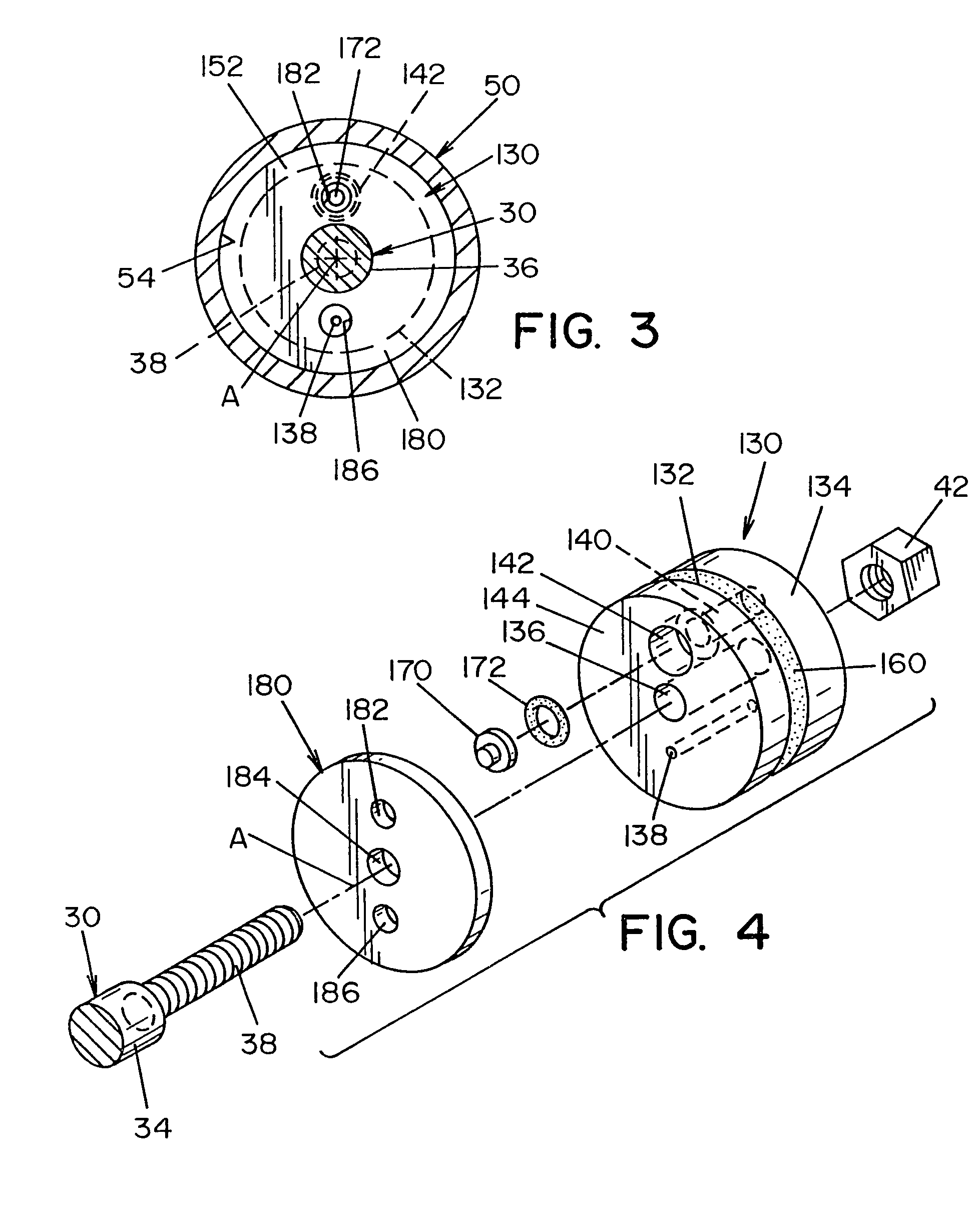
[0056]Referring now in greater detail to the drawings, wherein the showings are for the purpose of illustrating preferred embodiments of the invention only, and not for the purpose of limiting the invention, a compression spring system 20, in accordance with the invention, as shown in FIGS. 1-6, has an axis A and includes a spring rod 30 which is axially extendable and retractable relative to a one-piece tubular housing 50. The housing includes an internal chamber 52 having an inner surface 54, and a mount end 56 and an opposite end 60. Spring rod 30 includes an outer surface 36, an outer end 32 having a threaded end 40, and an inner end 34 having a threaded end 38. Inner end 34 is connected to guide member 130 by a nut 42 which is threaded on threaded end 38.

[0057]A first compression spring 120 and a second compression spring 122 are located in internal chamber 52. The two compression springs are oriented such that second compression spring 122 is surrounded by first compression sp...


PUM


Abstract

A spring system for relatively displacing elements attached to end mounts of the rod assembly comprises a housing having a rod member movable between extended and retracted positions relative thereto, and a first compression spring in the housing surrounded by a second compression spring for biasing the rod member to one of an extended or retracted position relative to the housing. The two springs are oppositely wound whereby, from a compressed condition, the spring rod exerts an expansion force which increases at a linear rate. The spring system includes a valve arrangement to control the rate at which the spring rod moves from a retracted position to an extended position.

Description

[0001]The present invention is claims priory on PCT / US03 / 00754 filed Jan. 10, 2003, which in turn is a continuation-in-part of co-pending U.S. patent application Ser. No. 10 / 056,941 filed Jan. 28, 2002.[0002]The present invention relates to compression spring rods, and more particularly to a spring and rod assembly that exerts an expansional force which increases at a substantially linear rate.INCORPORATION BY REFERENCE[0003]U.S. Pat. No. 6,199,843 to DeGrace; U.S. Pat. No. 6,179,099 to Koch, et al.; U.S. Pat. No. 5,810,339 to Küspert, et al.; and U.S. Pat. No. 4,962,916 to Palinkas are incorporated herein by reference as background information with regard to spring mechanisms. Also incorporated herein by reference is Assignee's U.S. patent application Ser. No. 10 / 056,941 filed Jan. 28, 2002.BACKGROUND OF THE INVENTION[0004]The present invention relates to compression spring rods such as a spring and rod assembly that exerts an expansional force which increases at a linear rate. The...

Claims


Application Information

Patent Timeline
IPC IPC(8): F16F1/04F16F9/02F16F13/00
CPCF16F9/0218F16F13/002
Inventor ADOLINE, JACK W.FISCHER, THOMAS J.
Owner BARNES GROUP
Why Eureka
Try Eureka