Implantable medical lead with biased electrode

a medical lead and electrode technology, applied in the field of medical devices, can solve the problems of undesirable phrenic nerve stimulation, non-optimal lv pacing electrode placement of lv lead electrodes, and general undesirable stimulation of neck muscles, and achieve the effect of increasing surface area

Inactive Publication Date: 2012-10-23
MEDTRONIC INC
View PDF126 Cites 86 Cited by
  • Summary
  • Abstract
  • Description
  • Claims
  • Application Information

AI Technical Summary

Problems solved by technology

Phrenic nerve stimulation is generally undesirable during LV pacing therapy.
In some instances, the implantable lead may need to be specifically positioned to avoid phrenic nerve stimulation during LV pacing therapy, which may result in placing the electrodes of the LV lead at a non-optimal site for LV pacing.
Stimulation of neck muscles is generally undesirable during therapeutic vagal stimulation.

Method used


Image

  • Implantable medical lead with biased electrode
  • Implantable medical lead with biased electrode
  • Implantable medical lead with biased electrode

Examples


Embodiment Construction

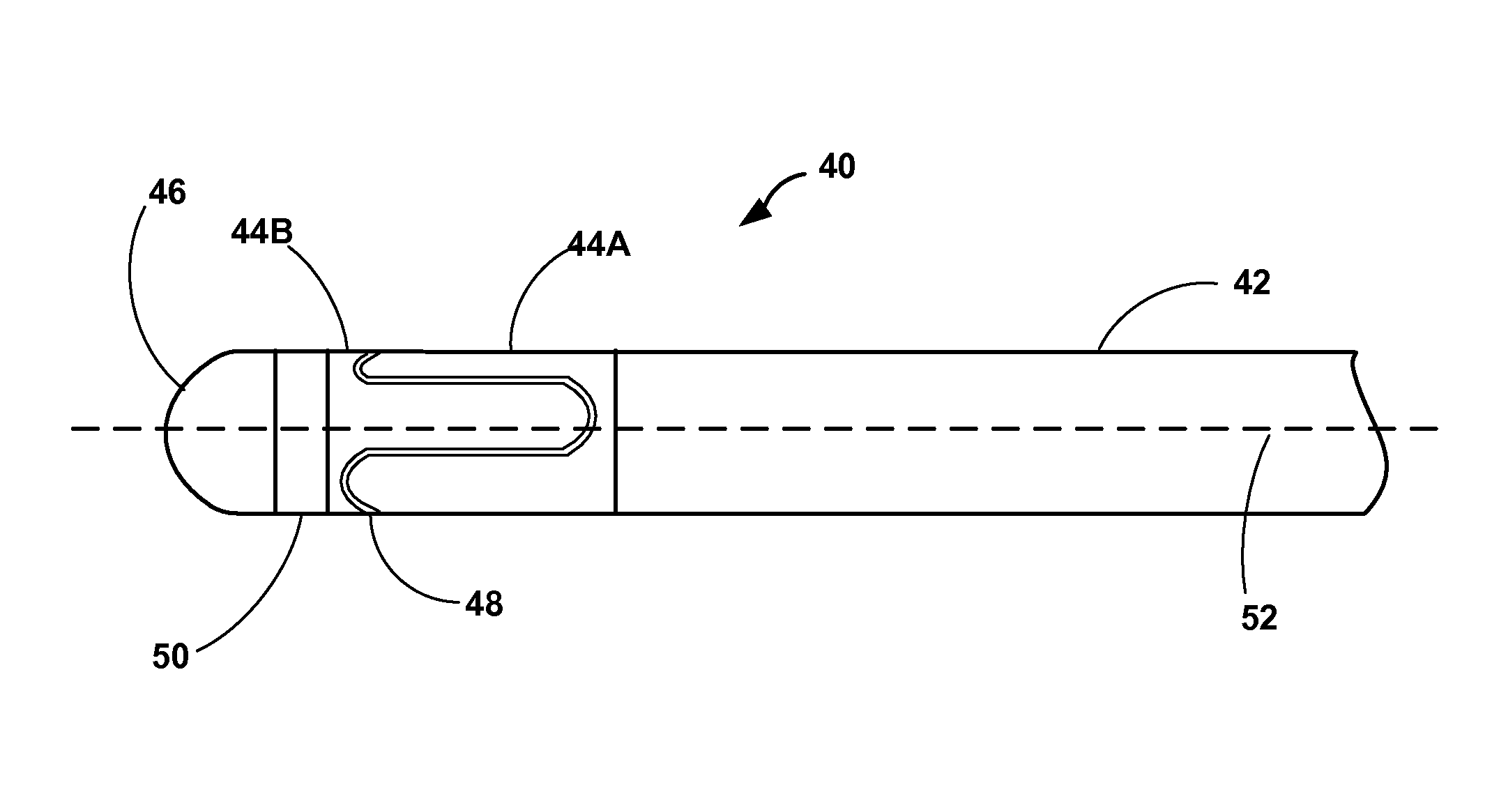
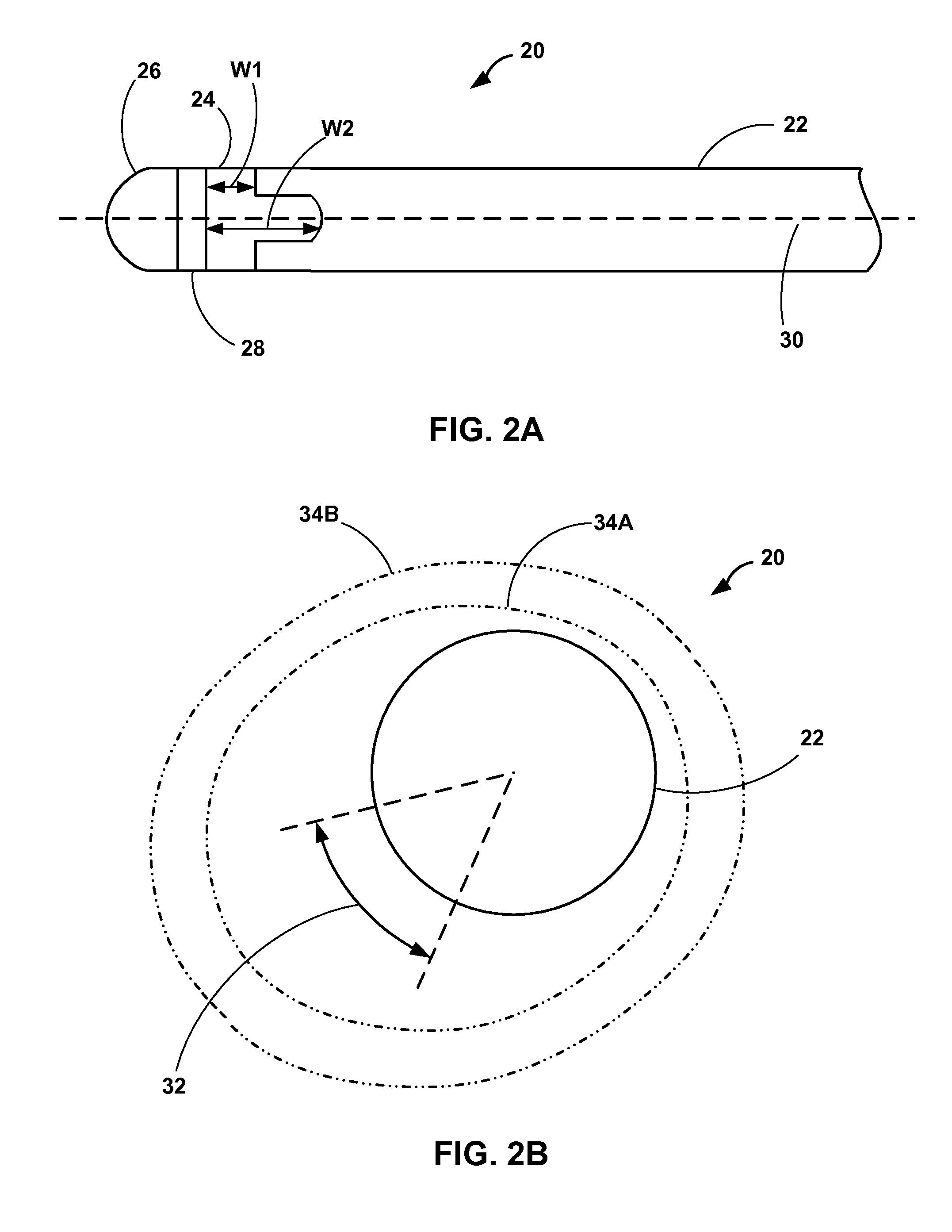
[0022]In general, the present disclosure is directed toward controlling the direction of propagation of a stimulation field. An implantable medical lead may include at least one biased ring electrode. A width of the biased ring electrode in a longitudinal direction of the lead varies about the perimeter of the lead. The biased electrode may aid in directing a stimulation field in a particular transverse or radial direction. For example, rather than distributing equally about the perimeter of the lead, the stimulation field may be biased to the portion or side of the lead where the biased electrode has an increased surface area. Controlling the direction of the stimulation field may be useful, for example, to avoid phrenic nerve stimulation during LV pacing or neck muscle stimulation during vagal neurostimulation.

[0023]While the description primarily refers to implantable medical leads and implantable medical devices, such as pacemakers and pacemaker-cardioverter-defibrillators, that...


PUM


Abstract

This disclosure describes implantable medical leads that include a lead body and an electrode. A width of the electrode as measured along a longitudinal direction of the lead varies about the perimeter of the lead. The uneven width of the electrode may bias a stimulation field in a particular direction, e.g., a radial or transverse direction relative to the longitudinal axis of the lead. Electrodes with an uneven width may be useful for controlling the direction of propagation of the stimulation field in order to, for example, avoid phrenic nerve stimulation during LV pacing or neck muscle stimulation during vagal neurostimulation.

Description

[0001]This application claims the benefit of U.S. Provisional Application No. 60 / 956,832, filed Aug. 20, 2007, U.S. Provisional Application No. 60 / 956,868, filed Aug. 20, 2007 and U.S. Provisional Application No. 61 / 049,226, filed Apr. 30, 2008, each of which are hereby incorporated by reference.TECHNICAL FIELD[0002]The present disclosure relates to medical devices, more particularly to implantable medical leads.BACKGROUND[0003]In the medical field, implantable leads are used with a wide variety of medical devices. For example, implantable leads are used with implantable cardiac pacemakers that provide therapeutic stimulation to the heart by delivering pacing, cardioversion or defibrillation pulses via the leads. Implantable cardiac pacemakers deliver such pulses via electrodes disposed on the leads, e.g., near distal ends of the leads. Implantable medical leads may be configured to allow electrodes to be positioned at desired cardiac locations so that the pacemaker can deliver puls...

Claims


Application Information

Patent Timeline
Patent Type & Authority Patents(United States)
IPC IPC(8): A61N1/05
CPCA61N1/05A61N1/056A61N1/0534A61N1/0551A61N2001/0585
Inventor EGGEN, MICHAEL D.SOMMER, JOHN L.EBERT, MICHAELBOURN, DAVID WAYNEMIYAZAWA, GABRIELA C.
Owner MEDTRONIC INC
Why Eureka
Try Eureka