
Electronic oscillation signal generation circuit

a technology of electronic oscillation and signal generation circuit, applied in pulse manipulation, pulse technique, instruments, etc., can solve problems such as unstable period of digital oscillation signal

Active Publication Date: 2012-10-30
AMICCOM ELECTRONICS CORP
View PDF1 Cites 0 Cited by
  • Summary
  • Abstract
  • Description
  • Claims
  • Application Information

AI Technical Summary

Benefits of technology

The solution ensures precise maintenance of the oscillation signal period and improves power efficiency by eliminating the need for continuous voltage level monitoring, resulting in a more stable and power-efficient electronic oscillation signal generation circuit.

Problems solved by technology

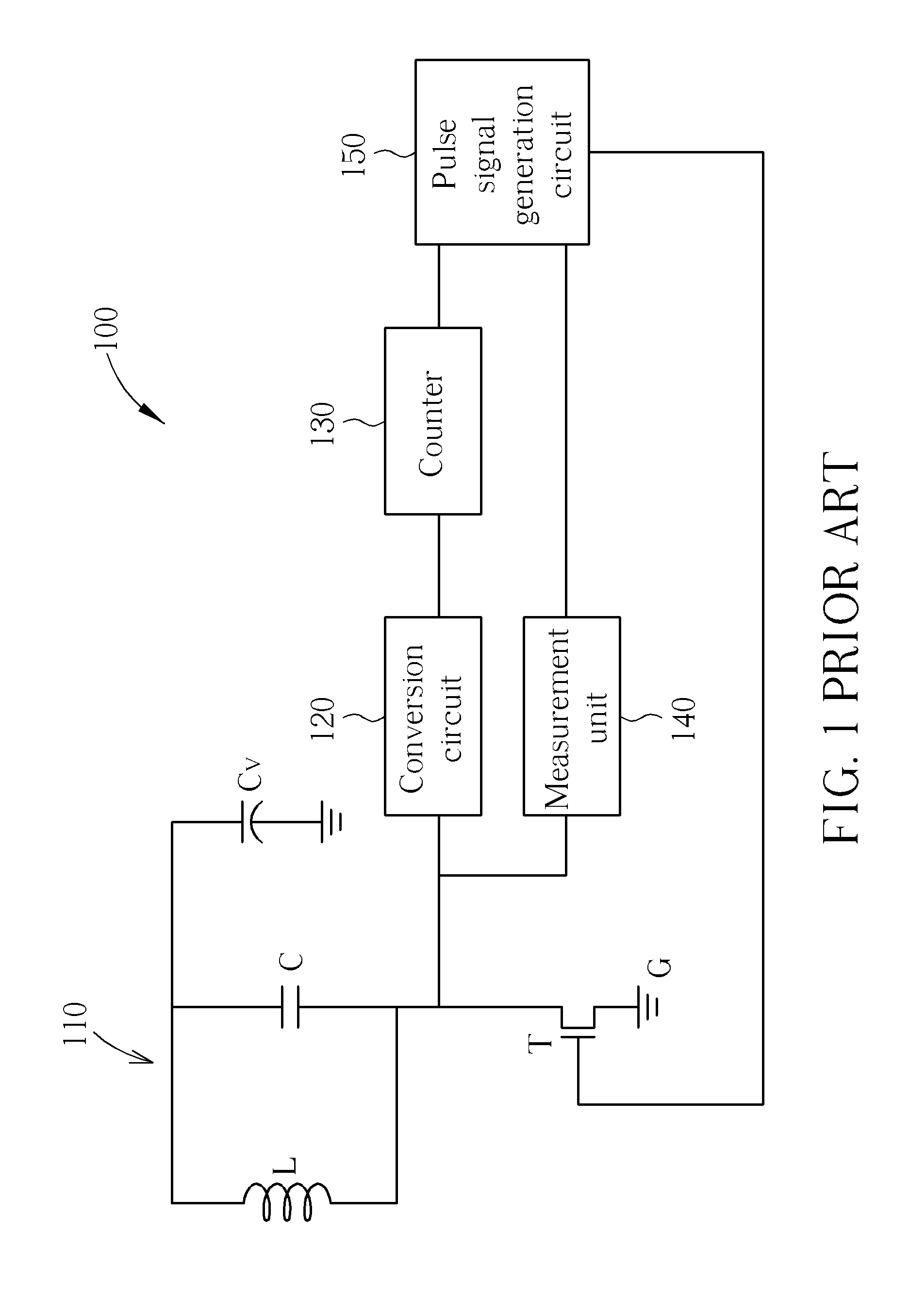
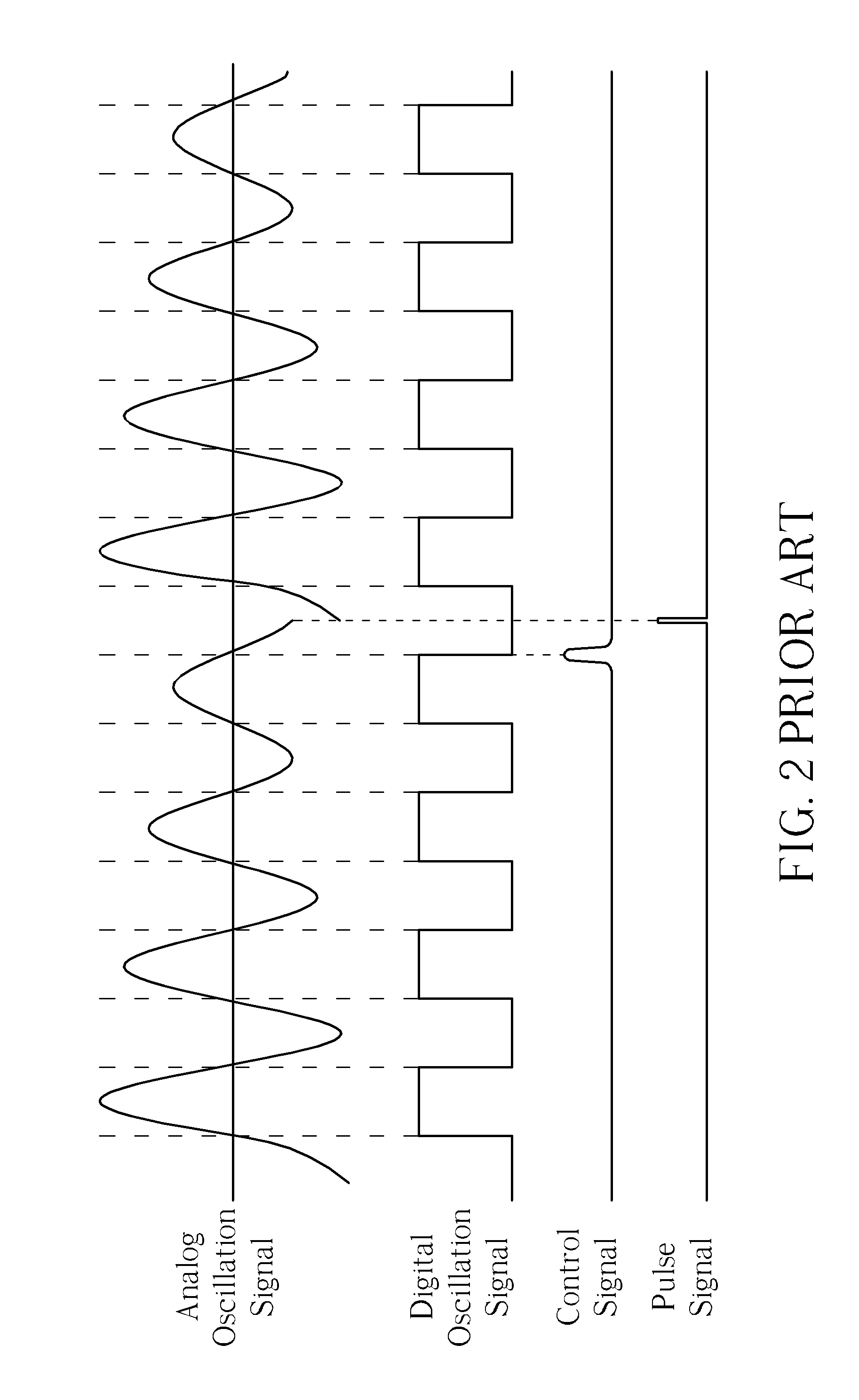
Therefore, the electronic oscillation signal generation circuit 100 of the prior art can not precisely detect when the analog oscillation signal reaches the trough, and thus makes the period of the digital oscillation signal unstable.

Method used


Image

  • Electronic oscillation signal generation circuit
  • Electronic oscillation signal generation circuit
  • Electronic oscillation signal generation circuit

Examples


Embodiment Construction

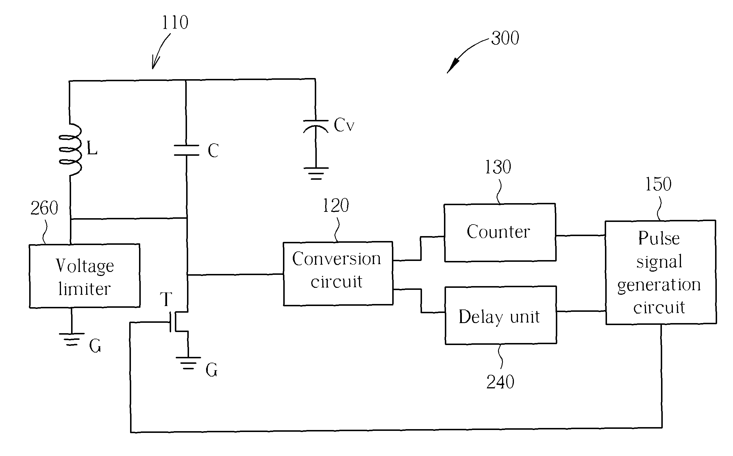
[0014]Please refer to FIG. 3. FIG. 3 is a diagram showing an electronic oscillation signal generation circuit 200 of the present invention. The electronic oscillation signal generation circuit 200 of the present invention comprises an electronic oscillation circuit 110, a charging capacitor Cv, a switch T, a conversion circuit 120, a counter 130, a delay unit 240, and a pulse signal generation circuit 150. The electronic oscillation circuit 110 comprises an inductor L and a capacitor C. The inductor L and the capacitor C are electrically connected to each other in parallel. The charging capacitor Cv is electrically connected to a first end of the electronic oscillation circuit 110 for providing a DC voltage to the electronic oscillation circuit 110. The switch T is for electrically connecting a second end of the electronic oscillation circuit 110 to ground G when the switch T is turned on, in order to allow electricity to flow to ground G from the charging capacitor Cv through the e...


PUM


Abstract

An electronic oscillation signal generation circuit includes an electronic oscillation circuit, a DC voltage source for providing a DC voltage to the electronic oscillation circuit, a switch for electrically connecting the electronic oscillation circuit to ground when the switch is turned on so as to generate an analog oscillation signal after the switch is turned off, a conversion circuit for converting the analog oscillation signal to a digital oscillation signal, a counter for generating a control signal when the digital oscillation signal reaches a predetermined number of periods, a delay unit for generating a delay signal a predetermined time after a falling edge of the digital oscillation signal is triggered, and a pulse signal generation circuit electrically connected to the counter and the delay unit for generating a pulse signal according to the control signal and the delay signal so as to turn on the switch.

Description

BACKGROUND OF THE INVENTION[0001]1. Field of the Invention[0002]The present invention relates to an electronic oscillation signal generation circuit, and more particularly, to an electronic oscillation signal generation circuit utilizing a counter and a delay unit for maintaining amplitude and a period of an electronic oscillation signal.[0003]2. Description of the Prior Art[0004]Please refer to FIG. 1 and FIG. 2. FIG. 1 is a diagram showing an electronic oscillation signal generation circuit 100 of the prior art. FIG. 2 is a diagram showing related signals of the electronic oscillation signal generation circuit 100 of FIG. 1. The electronic oscillation signal generation circuit 100 of the prior art comprises an electronic oscillation circuit 110, a charging capacitor Cv, a switch T, a conversion circuit 120, a counter 130, a measurement unit 140, and a pulse signal generation circuit 150. The electronic oscillation circuit 110 comprises an inductor L and a capacitor C. The inductor...

Claims


Application Information

Patent Timeline
Patent Type & Authority Patents(United States)
IPC IPC(8): H03K3/017
CPCH03B5/1228H03B5/1203H03L7/00H03L5/00H03B2200/0046
Inventor HSU, HSIN-CHINLIN, FANG-LIH
Owner AMICCOM ELECTRONICS CORP
Learn More