
Transformer assembly

a transformer and assembly technology, applied in the direction of transformer/inductance cooling, electrical equipment, basic electric elements, etc., can solve the problems of economic losses for utilities/users, electric transformers may be subject to explosions and fires,

Active Publication Date: 2012-10-30
ABB POWER GRIDS SWITZERLAND AG
View PDF22 Cites 3 Cited by
  • Summary
  • Abstract
  • Description
  • Claims
  • Application Information

AI Technical Summary

Benefits of technology

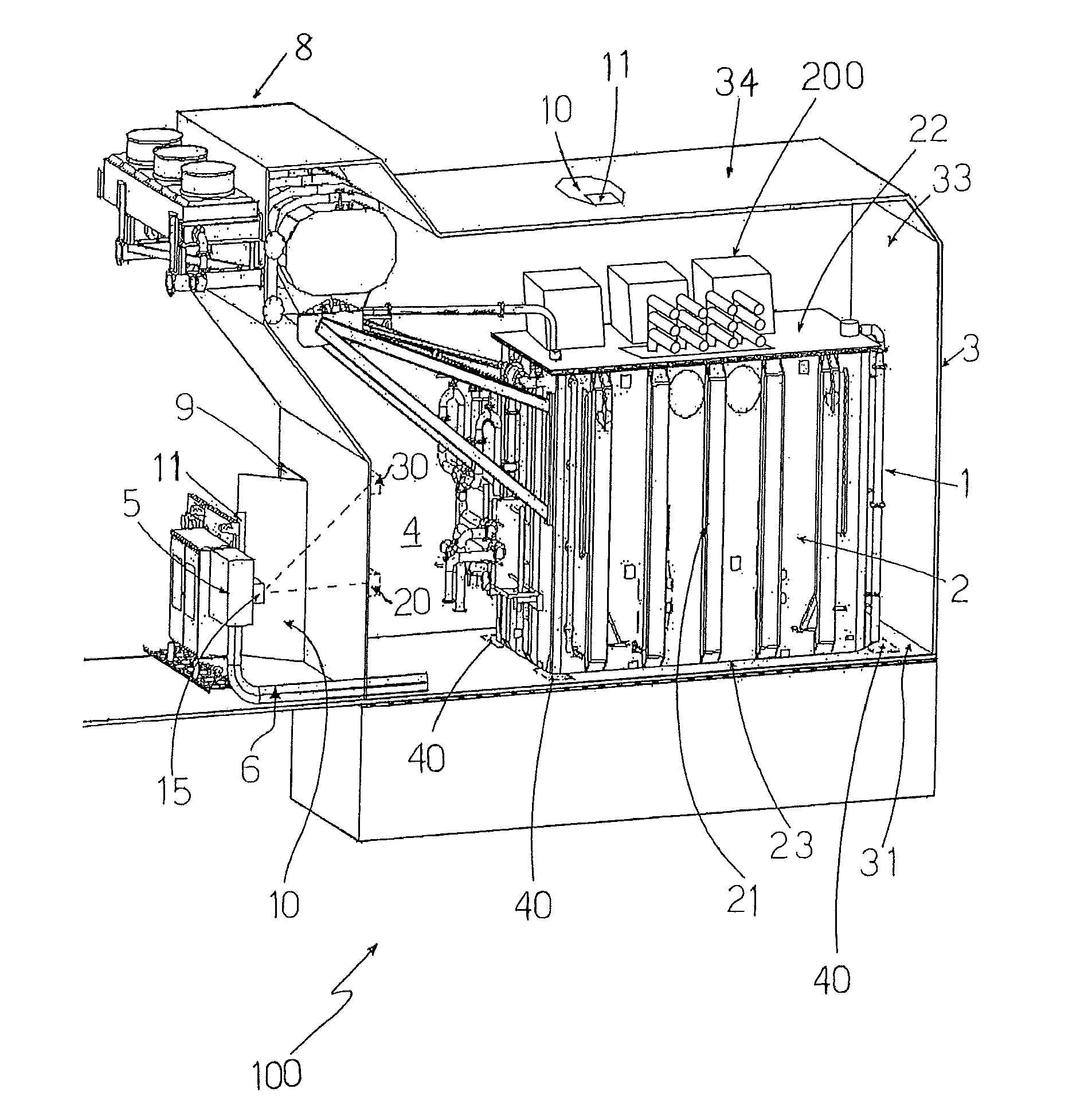
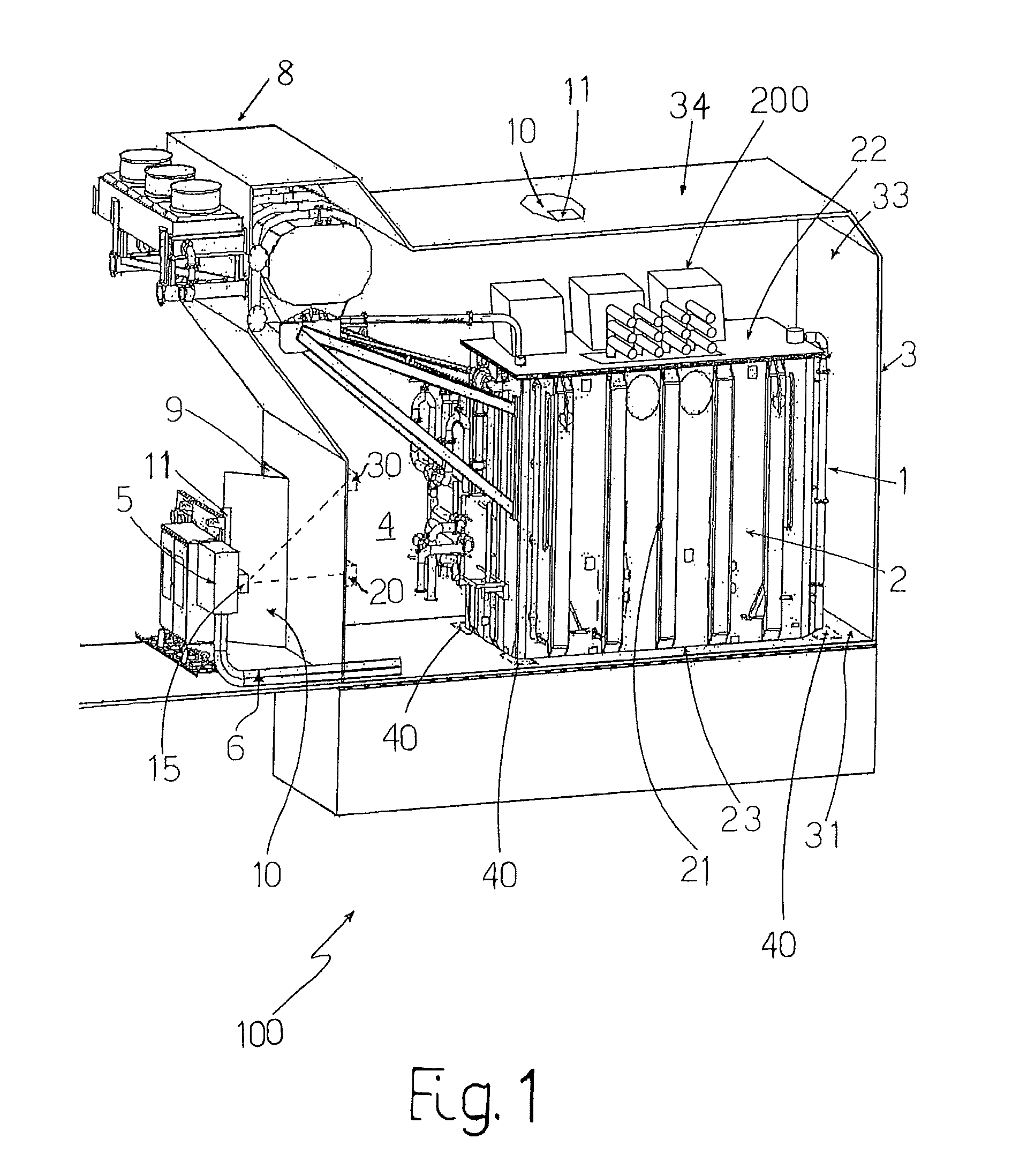
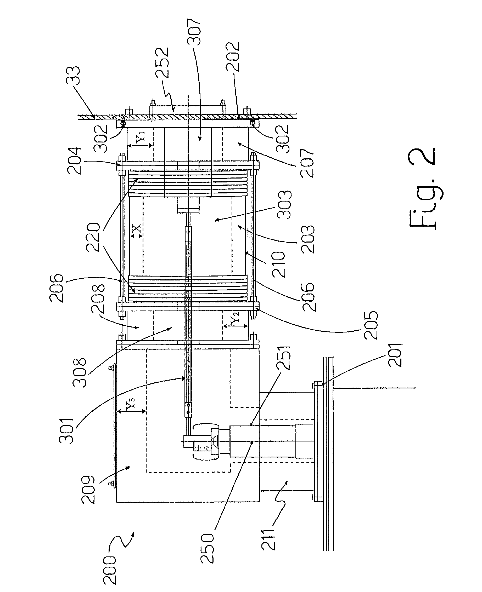
[0091]In practice, it has been found that an exemplary transformer assembly according to the disclosure can provide advantages and improvements with respect to known solutions. In fact, the connection device 200 can allow an easy, precise, and safe connection between each phase of the transformer 1 and electrical parts positioned outside the housing 3. If under normal working conditions, there is an explosive event occurring into any of the devices 200, the rupture of one of the pieces of its body (e.g., the hollow cylinder 203) allows discharging the effects of such explosion into the housing 3. Also when an explosion occurs within the transformer 1, the housing 3 can contain such an explosion due to the above described structure. In addition, the gaseous atmosphere inside the space 4 can be monitored and regulated so that the content of oxygen is below or equal to the first threshold thus resulting in a substantially fire-inert gas atmosphere (e.g., an atmosphere suitable to prevent ignition of fires, or at least to fast suppress their propagation). When it is desired for personnel to enter the space 4 inside the housing 3, the conditioning means previously described can allow increasing of the level of oxygen up to or above the second indicated threshold, thereby creating a breathable environment inside the housing 3.

Problems solved by technology

During their working life electrical transformers may be subject to explosions and fires; these events can be triggered for example by electrical arcs and are fed by the energy flowing from the electrical grid into the transformer.
The effects of such explosions and fires can be very dangerous and may cause severe damages to the transformer and to the various equipment / loads operatively coupled therewith, and disruption of the energy transportation even for long periods, thus resulting in economic losses for utilities / users.

Method used


Image

  • Transformer assembly
  • Transformer assembly
  • Transformer assembly

Examples


Embodiment Construction

[0019]An exemplary transformer assembly is disclosed and comprises:[0020]an electrical transformer comprising a transformer tank having a plurality of side walls, a top wall, and a base wall;[0021]a housing having a base wall, a plurality of side walls, and a top wall, said transformer tank being positioned inside said housing; and[0022]a device for electrically connecting said transformer to an electrical article outside said housing, said connecting device comprising a shaped body having a first face which is suitable to be connected to one of said top, base or side walls of the tank, and a second face which is suitable to be connected to one of said base, top, or side walls of the housing, wherein said shaped body comprises at least one deformable portion which is adapted to adjust the positioning of said second face relative to said one of said base, top, or side walls of the housing, to which it is suitable to be connected to.

[0023]FIG. 1 is a perspective view (partially cut in...


PUM

PropertyMeasurementUnit
thicknessaaaaaaaaaa
thicknessaaaaaaaaaa
internal volumeaaaaaaaaaa

Abstract

A transformer assembly is disclosed which includes a housing and an electrical transformer having a tank which is positioned inside the housing. A device for electrically connecting the transformer to an electrical article outside the housing includes a shaped body having a first face which is suitable to be connected to one of the walls of the tank, and a second face which is suitable to be connected to one of the walls of the housing. The shaped body can include a deformable portion which is adapted to adjust the positioning of the second face relative to the wall of the housing to which it is suitable to be connected.

Description

RELATED APPLICATION[0001]This application claims priority as a continuation application under 35 U.S.C. §120 to PCT / EP20086 / 063343 filed as an International Application on Oct. 6, 2008 designating the U.S., the entire content of which is hereby incorporated by reference in its entiretyFIELD[0002]The present disclosure relates to a transformer assembly for transmitting and / or distributing electrical power.BACKGROUND INFORMATION[0003]It is known in the art the use of electrical transformers, such as power transformers, for transmitting and distributing electricity through electrical grids.[0004]A task of an electrical transformer is to allow exchanging electric energy between two or more electrical systems of different voltages by stepping up or down the level of voltage.[0005]During their working life electrical transformers may be subject to explosions and fires; these events can be triggered for example by electrical arcs and are fed by the energy flowing from the electrical grid i...

Claims


Application Information

Patent Timeline
Patent Type & Authority Patents(United States)
IPC IPC(8): H01F27/02H01F27/10H01F27/04
CPCH01F27/04H01F27/02H01H9/046
Inventor SCIAN, ILARIOFOGELBERG, THOMAS
Owner ABB POWER GRIDS SWITZERLAND AG
Learn More