Connecting assembly and scanning electron microscope main rack

A technology for connecting components and scanning electron microscopes, which is applied in the direction of connecting members, thin plate connections, mechanical equipment, etc., can solve the problems of inconvenient installation and disassembly of the main frame and the column, and achieve the effect of reliable connection and simple operation.

Inactive Publication Date: 2019-03-08
KYKY TECH
View PDF6 Cites 0 Cited by
  • Summary
  • Abstract
  • Description
  • Claims
  • Application Information

AI Technical Summary

Problems solved by technology

[0005] Therefore, the technical problem to be solved by the present invention is to overcome the inconvenient installation and disassembly of the main frame and the column of the existing products, ...

Method used


Image

  • Connecting assembly and scanning electron microscope main rack
  • Connecting assembly and scanning electron microscope main rack
  • Connecting assembly and scanning electron microscope main rack

Examples


Embodiment 1

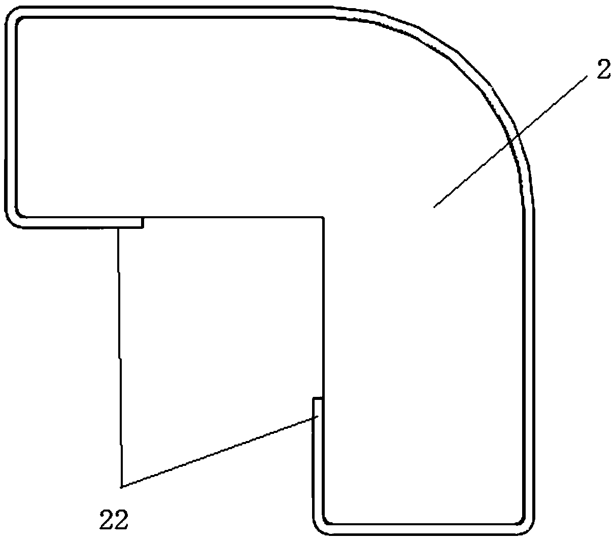
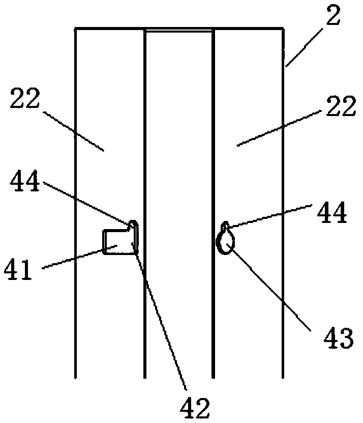
[0039] A connection component of this embodiment, such as figure 1 - Figure 4 As shown, it is arranged on the first piece 1 and the second piece 2, the first piece 1 has a group of adjacent two first side surfaces 11; the second piece 2 is L-shaped, with adjacent The two second sides 22 connected to the two first sides 11 , the inner sides of the second sides 22 are connected to the first side 11 . The connecting assembly includes a first connecting piece 3 , a second connecting piece and a sliding groove 41 .

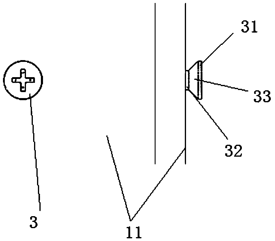
[0040] There are two first connecting parts 3 , which are respectively arranged on the two first side surfaces 11 , and the connecting line between the two first connecting parts 3 is parallel to the horizontal plane. The first piece 1 includes a head 31 , a connecting portion 33 and a fixing portion 32 . The head 31 is used to be inserted into the second connector, the fixing part 32 is fixedly connected to the first part 1, and the connecting part 33 is arranged ...

Embodiment 2

[0054] The scanning electron microscope main frame of the present embodiment, as Figure 5 As shown, the connection assembly of the first embodiment is included.

[0055] The main body of the main frame is the first piece 1, which is used to set up the scanning electron microscope.

[0056] The upright column is the second part 2, and the upright column is L-shaped, and is hooked to the main frame main body through the connecting assembly.

[0057] In this embodiment, the main body of the main frame has four edges, and upright columns need to be arranged at the four edges.

[0058] When the column is installed on the main body of the main frame, it can rely on the gravity of the column and the V-shaped groove to self-lock on the main body of the main frame. The installation and disassembly of the column are relatively simple.


PUM


Abstract

The invention relates to the technical field of connecting devices, in particular to a connecting assembly and a scanning electron microscope main rack. The connecting assembly comprises at least twofirst connecting elements, at least two second connecting elements and at least one sliding groove. The first connecting elements are arranged on two first lateral sides correspondingly; the second connecting elements are arranged on two second lateral sides and correspond to the first connecting elements; the sliding groove is at least formed in one first lateral side or one second lateral side and communicates with the first connecting elements or the second connecting elements, and one second connecting element or one first connecting element can move back and forth in the sliding groove; and a first workpiece and a second workpiece move towards each other, and one second connecting element or one first connecting element moves in the sliding groove until into the corresponding first connecting element or the corresponding second connecting element and to be in insert connection with the first connecting element or the second connecting element, so that the first workpiece and the second workpiece are connected. The connecting assembly and the scanning electron microscope main rack have the advantage that the main rack and stand columns are convenient to mount and dismount.

Description

technical field [0001] The invention relates to the technical field of connection devices, in particular to a connection assembly and a main frame of a scanning electron microscope. Background technique [0002] The scanning electron microscope is an electron optical instrument that scans the surface of the sample line by line with a focused electron beam. The electron beam bombards the surface of the sample to generate secondary electrons or backscattered electrons. The secondary electrons or backscattered electrons generated on the surface are collected, and the scanning position of the electron beam on the surface of the sample and the number of secondary electrons or backscattered electrons generated are represented in the form of a two-dimensional image, that is, the secondary electrons of the scanning electron microscope are obtained. image or backscattered electron image. The resolution of scanning electron microscope images can reach the nanometer level or even bett...

Claims


Application Information

Patent Timeline
IPC IPC(8): F16B5/12F16B5/02G01N23/2251
CPCF16B5/02F16B5/123F16B5/126G01N23/2251
Inventor 孟祥良
Owner KYKY TECH
Why Eureka
Try Eureka