Disk drive having mounting inserts with cantilevered beams

a technology of mounting inserts and disk drives, which is applied in the direction of data recording, instruments, undesired vibration/sound insulation/absorption, etc., can solve the problems of vibration and acoustic disturbance caused by the operation of the disk drive itself, the surface of magnetic hard disks on which information is stored may be damaged by collisions with other internal components, and the transmission of mechanical shocks or environmental vibrations to the disk drive housing via its mounts

Active Publication Date: 2012-10-30
WESTERN DIGITAL TECH INC
View PDF43 Cites 61 Cited by
  • Summary
  • Abstract
  • Description
  • Claims
  • Application Information

AI Technical Summary

Problems solved by technology

Many disk drives include internal components that are sensitive to environmental contamination, and mechanical shocks and vibrations from outside the disk drive.
For example, the surfaces of magnetic hard disks on which information is stored may be damaged by collisions with other internal components (e.g. read / write heads and / or supporting arms and / or loading ramps).
In that case also, mechanical shocks or environmental vibrations may be transmitted to the disk drive housing via its mounts.
Specifically, vibration and acoustic disturbances caused by the operation of the disk drive itself may be undesirable if transmitted to a corresponding host computer system and / or consumer electronics device.
The designer of the housing and / or mounts for a disk drive faces a challenge that is compounded by several requirements and constraints.
For example, the mounting systems and housings for modern disk drives must meet very tight cost requirements, and typically must also meet dimensional limitations imposed by industry-standard “form factor” requirements.
Such cost and dimensional constraints create a design tendency towards simple and relatively stiff mounting solutions that may unintentionally exacerbate the transmission of mechanical shocks, vibration, and acoustic disturbances.
However, such electrical connection typically also entails an additional mechanical connection that can provide an additional path for transmission of mechanical shock, vibration, and acoustic disturbances.
This, in turn, may unacceptably reduce the effectiveness of conventional mechanical shock, vibration, and / or acoustic isolation methods and / or components.

Method used


Image

  • Disk drive having mounting inserts with cantilevered beams
  • Disk drive having mounting inserts with cantilevered beams
  • Disk drive having mounting inserts with cantilevered beams

Examples


Embodiment Construction

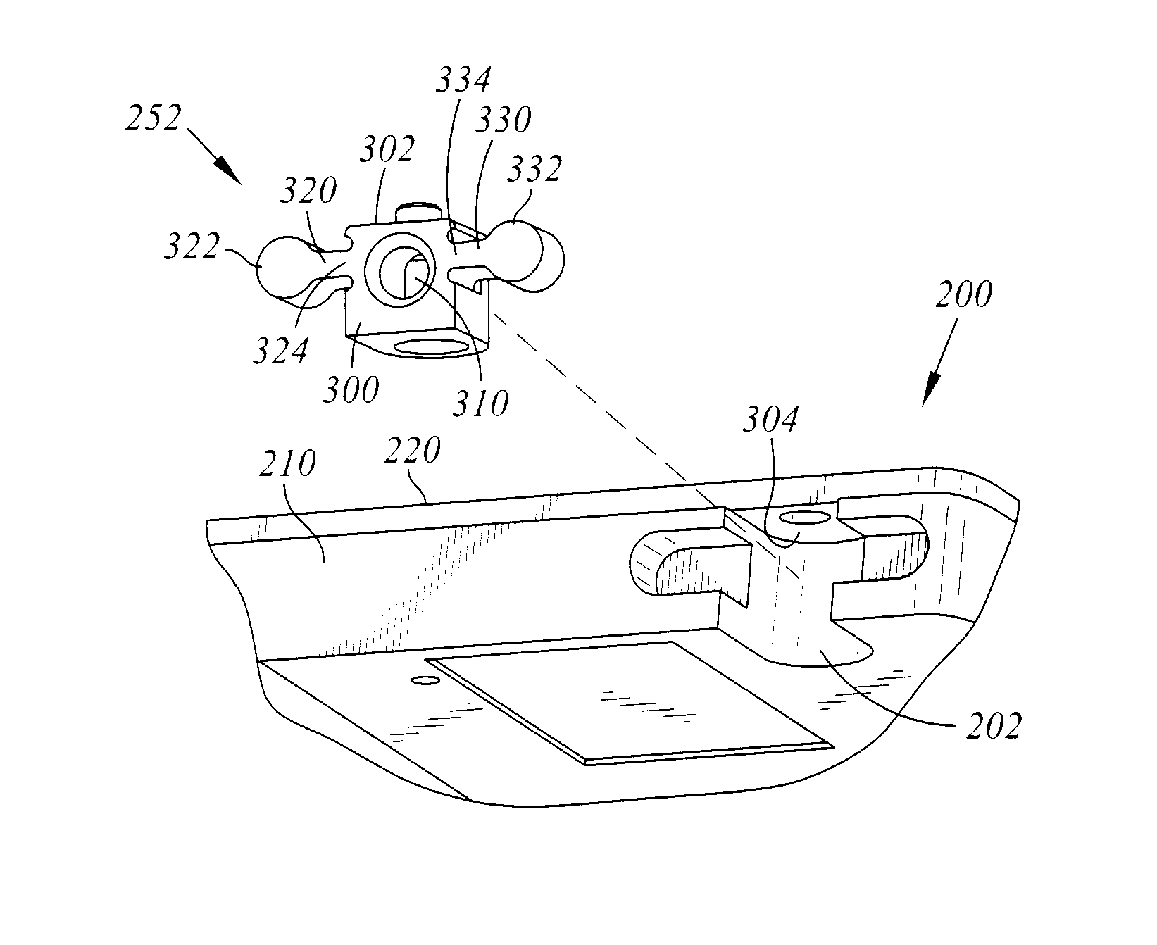
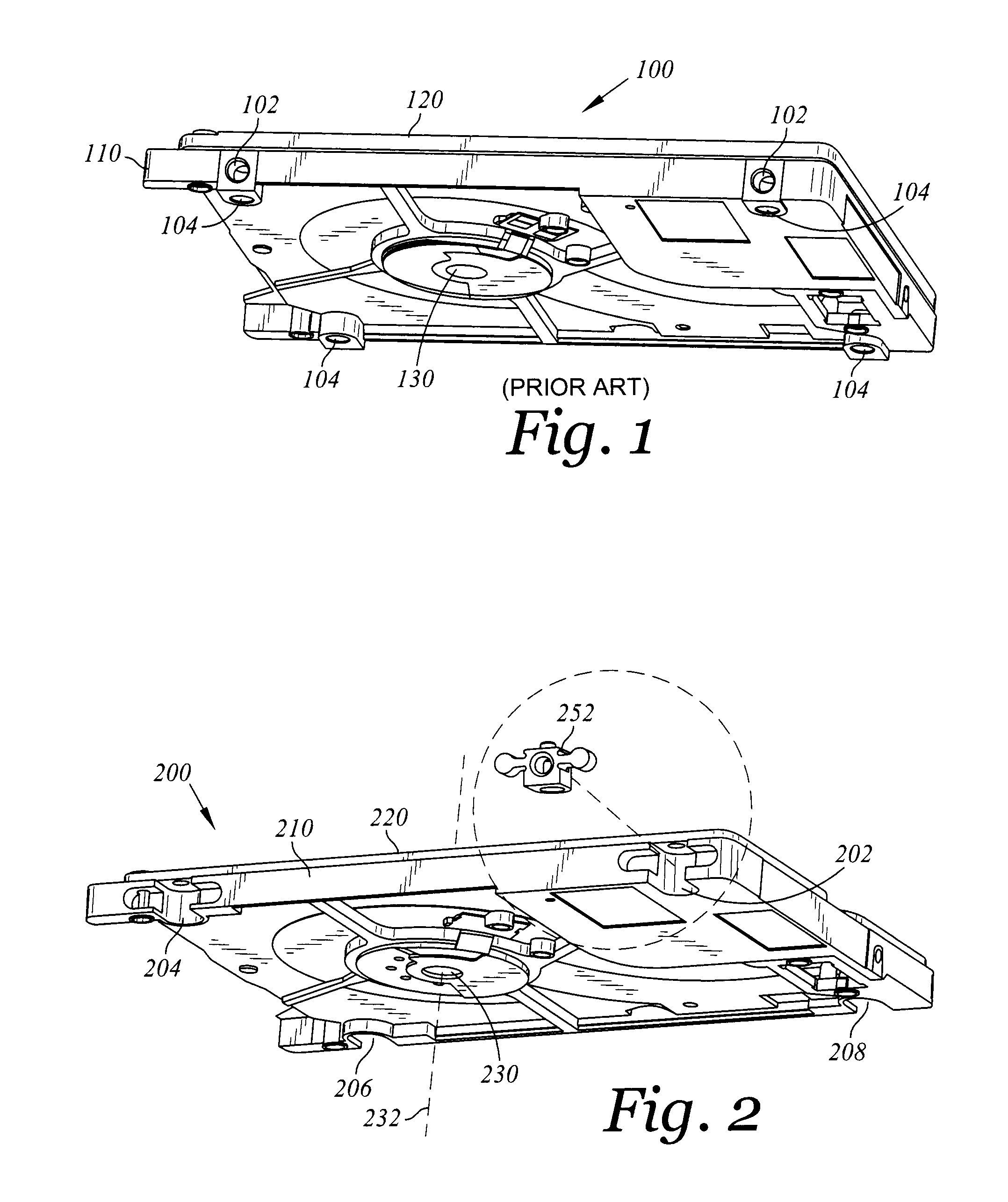
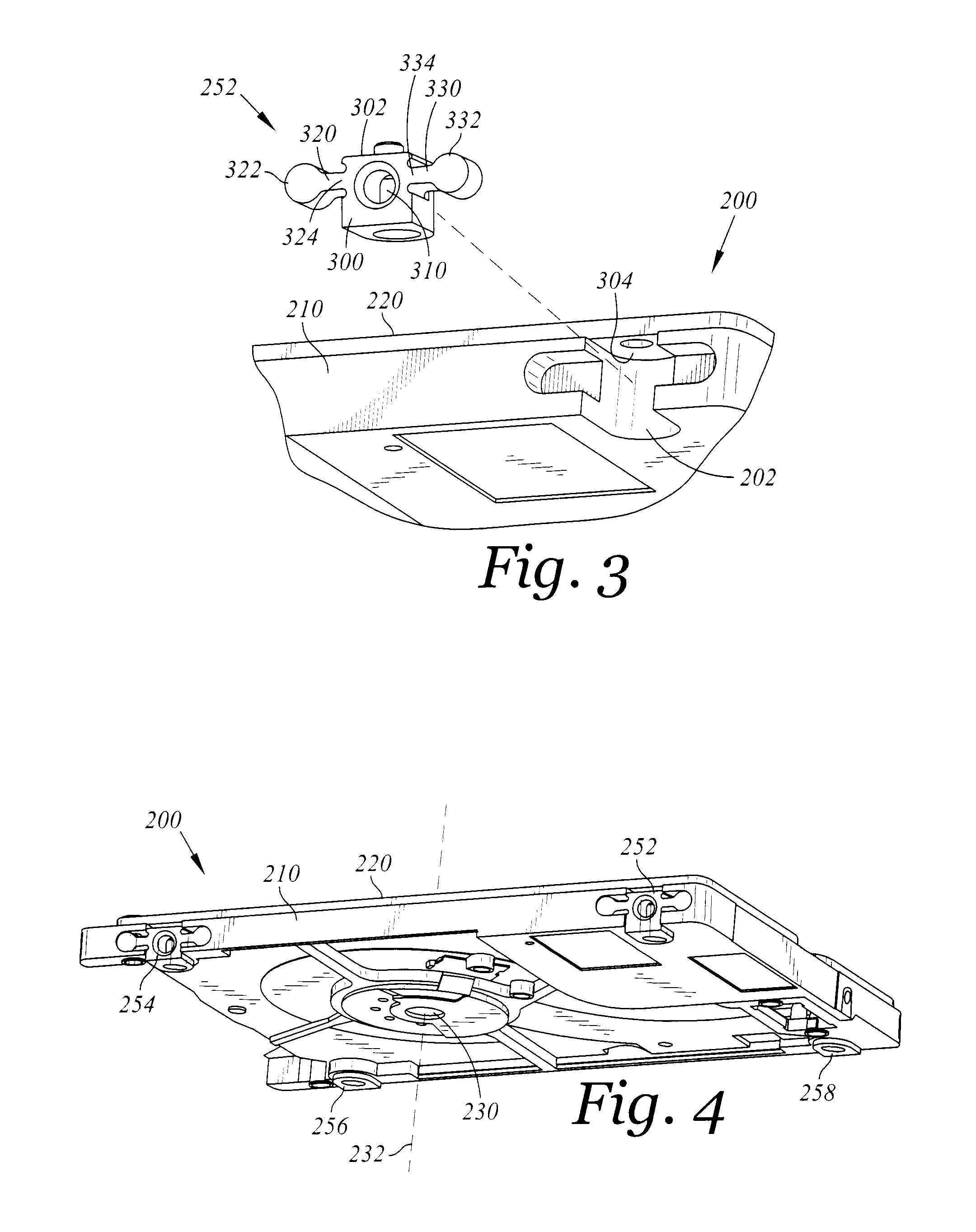
[0020]FIG. 2 depicts an exploded underside perspective view of a disk drive 200 for use with a host computer system, according to an embodiment of the present invention. Disk drive 200 includes a disk drive base 210 that includes a plurality of mounting recessions 202, 204, 206, and 208. The disk drive 200 also includes a spindle 230 defining an axis of rotation 232, and being rotably attached to the disk drive base 210. The spindle 230 supports and controls the rotation of an attached disk about the spindle axis of rotation 232, the disk serving as a storage media for information stored and / or accessed by the disk drive 200. The disk is not shown in FIG. 2 because it is enclosed within the disk drive housing that is formed by the disk drive base 210 and the cover 220. Similarly, only the bottom face of the spindle shaft of spindle 230 is visible in FIG. 2, having been press-fit into a hole in the disk drive base 210 from the other side (or otherwise conventionally attached to the d...


PUM

PropertyMeasurementUnit
axis of rotationaaaaaaaaaa
diameteraaaaaaaaaa
thicknessaaaaaaaaaa

Abstract

A novel disk drive includes a disk drive base that includes a plurality of mounting recessions. Each of a plurality of mounting inserts at least partially protrudes into a respective one of the plurality of mounting recessions, and contacts the disk drive base. Each of the plurality of mounting inserts includes a body portion that is adapted to be attached to a host computer system. Each of the plurality of mounting inserts also includes at least one cantilevered beam having a root end that is attached to the body portion and having a distal end that is in contact with the disk drive base in a respective one of the plurality of mounting recessions. The root end is not in contact with the disk drive base when the mounting insert is in an undeformed state.

Description

BACKGROUND OF THE INVENTION[0001]1. Field of the Invention[0002]The present invention relates generally to the field of information storage devices, and more particularly to mounting systems and housings for disk drives.[0003]2. Background of the Art[0004]Disk drives are used to retrieve and / or store data for computer systems and other consumer electronics products. Examples of disk drives include magnetic hard disk drives, optical disk drives, magneto-optical disk drives, and removable-media disk drives. Many disk drives include internal components that are sensitive to environmental contamination, and mechanical shocks and vibrations from outside the disk drive. For example, the surfaces of magnetic hard disks on which information is stored may be damaged by collisions with other internal components (e.g. read / write heads and / or supporting arms and / or loading ramps). Such internal components are typically enclosed within a disk drive housing. For example, FIG. 1 depicts a disk dri...

Claims


Application Information

Patent Timeline
Patent Type & Authority Patents(United States)
IPC IPC(8): G11B33/14
CPCG11B25/043G11B33/08
Inventor LARSON, NILS E.EDWARDS, JOHN R.MYERS, DAVID K.
Owner WESTERN DIGITAL TECH INC
Why Eureka
Try Eureka