Boarding bridge

a technology for boarding bridges and passage members, applied in bridges, ground installations, constructions, etc., can solve problems such as difficulty in passing through the boarding bridge, passenger trip and fall on the portion of the step, and the tension applied to the passage member by the spring member can be substantially constant, simple and inexpensive manufacturing

Active Publication Date: 2012-11-06
MITSUBISHI HEAVY INDS TRANSPORTATION EQUIP ENG & SERVICE
View PDF5 Cites 8 Cited by
  • Summary
  • Abstract
  • Description
  • Claims
  • Application Information

AI Technical Summary

Benefits of technology

[0017]The passage member includes a walkway passage portion with at least a predetermined length in the longitudinal direction from one end side, that is, a length from one end to the first guiding members when the outer passage section has moved the maximum distance toward the distal end side. Thus, when the outer passage section and the inner passage section move relatively in the longitudinal direction, it is possible to form a walkway passage portion that has a length that is equivalent to the amount of this movement. In addition, because a tension is applied to the passage member by the spring member, it is possible to form a stable walkway passage.
[0032]In addition, the structure can be simply and inexpensively manufactured, and the structure is difficult to damage and is strong.

Problems solved by technology

However, because the passage sections are telescopically fit, there are level differences in the passages of adjacent passage sections, and there is a concern that passengers may trip and fall on these level differences.
However, the device that bridges the steps as disclosed in Japanese Unexamined Patent Application, First Publication No. 2004-80770, does not eliminate the steps in a fundamental manner, and thus there remains, as before, the concern that a passenger may trip and fall at the portion of the step.
In addition, there is the problem that for a passenger in a wheel chair, passing through the boarding bridge may be difficult.

Method used


Image

  • Boarding bridge
  • Boarding bridge
  • Boarding bridge

Examples


Embodiment Construction

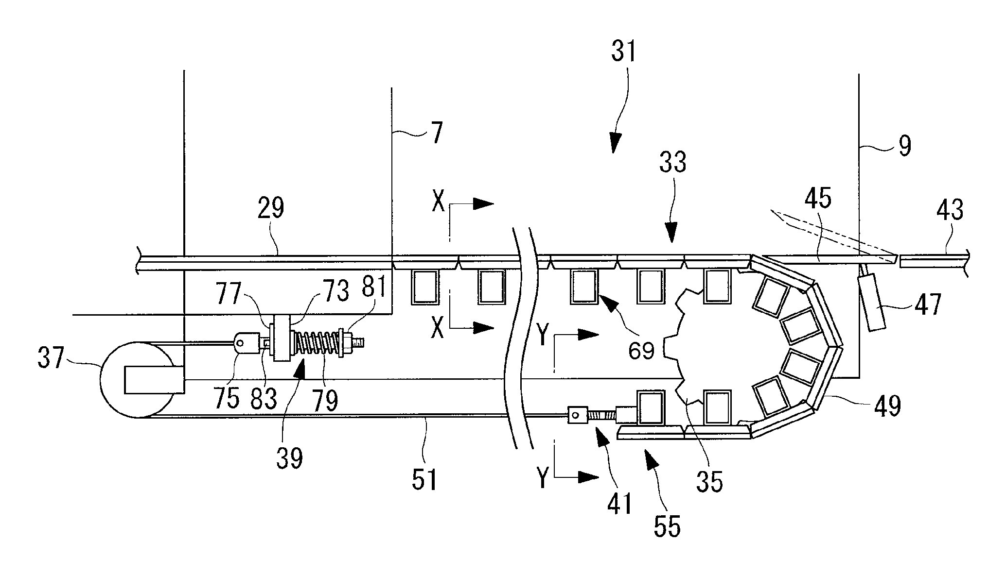
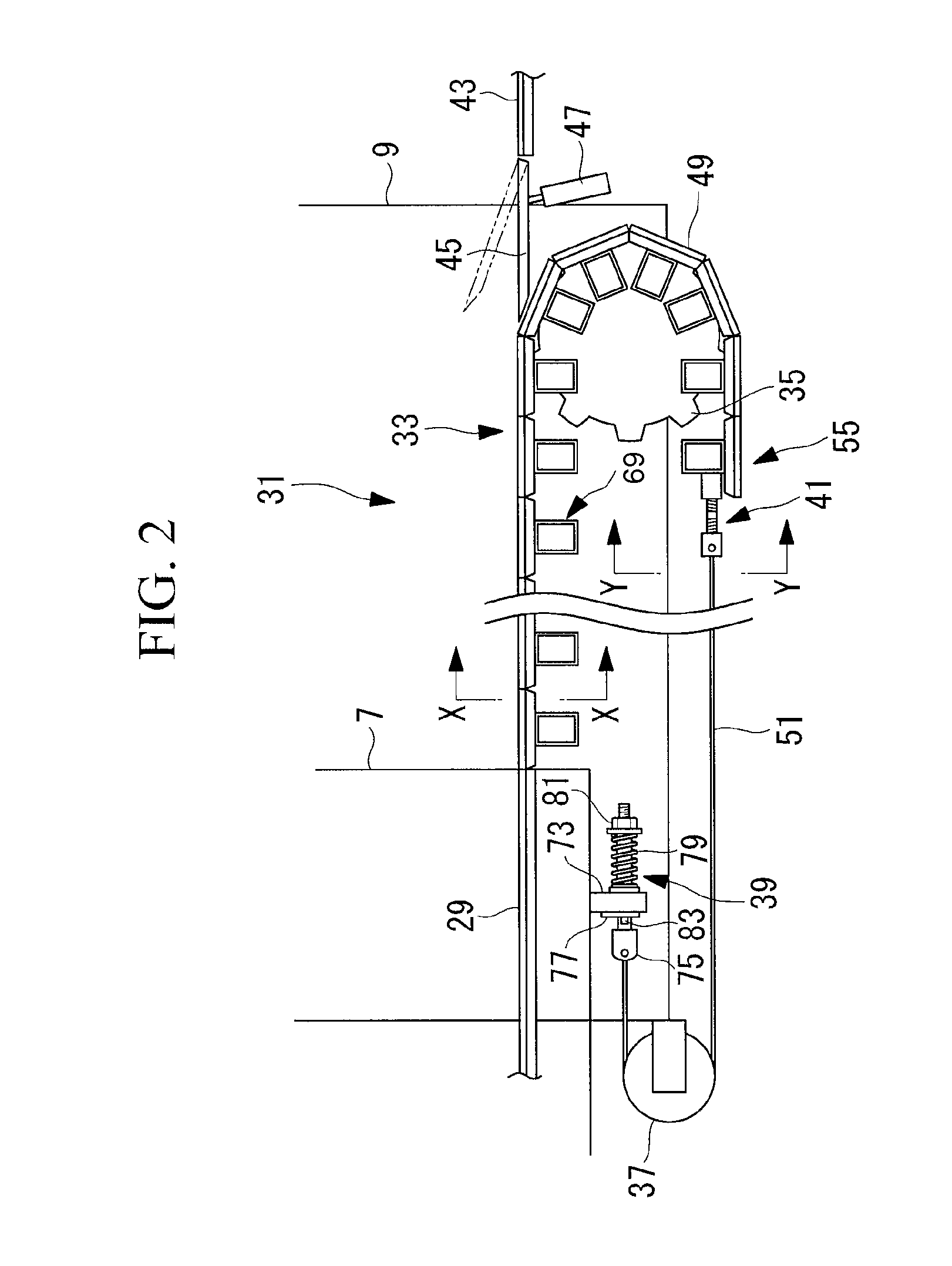
[0055]Below, the embodiments of the present invention will be explained with reference to FIG. 1 to FIG. 7, which are examples of a boarding bridge 1 in which a tunnel portion that extends and retracts is formed by two tunnels.

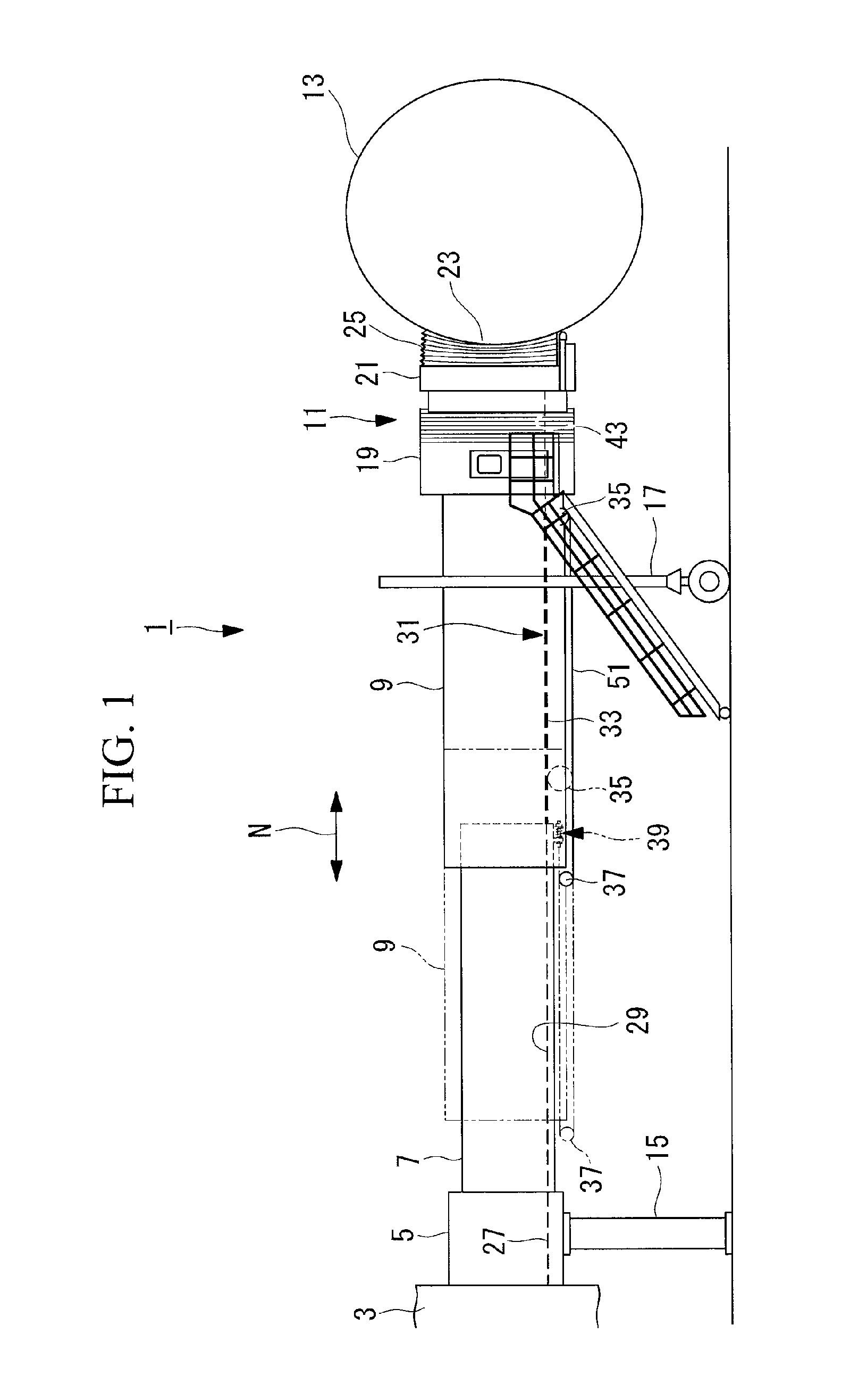
[0056]FIG. 1 is a frontal view that shows the overall schematic structure of the boarding bridge 1.

[0057]The boarding bridge 1 links an airport terminal building and an aircraft 13, and forms a walkway for passengers between the terminal building and the aircraft 13. The boarding bridge 1 enables direct boarding and deboarding.

[0058]The boarding bridge 1 is provided with a rotunda 5 that is provided so as to be fixed to a stationary bridge 3 that passes to the terminal building; a proximal end tunnel (passage section, inner passage section) 7 that is connected to the rotunda so as to be rotatable in a horizontal direction; a distal end tunnel (passage section, outer passage section) 9 that telescopically fits over the distal end side (the aircraft 13 side) of ...


PUM


Abstract

A boarding bridge is provided that has an inexpensive, trouble-free, and strong construction, that eliminates the level differences between the passage portions of adjacent passage sections, and can reduce the occurrence of passengers falling and the like. In the boarding bridge (1), a proximal end tunnel (7) and a distal end tunnel (9) are telescopically fit, and are extended and retracted by moving relative to each other in a longitudinal direction. At the passage portion of the distal end tunnel (9) are provided a passage member (33) having, at a passage portion of the distal end tunnel (9), one end thereof connected to the end portion of the stationary passage (29) of the proximal end tunnel (7), having a distal end passage portion (31) that has at least a predetermined length in a longitudinal direction, and having the other end thereof installed at the proximal end tunnel (7); sprockets (35) that are installed at the lower portion of the distal end tunnel of the distal end tunnel (9) such that the position thereof does not move, and that guide the passage member (33) in a vertical direction; a sheave (37) that is installed at the lower portion of the back end portion of the distal end tunnel (9) such that the position thereof does not move, and that guides the passage member (33) in a vertical direction; and a spring member (39) that applies a tension to the passage member (33).

Description

BACKGROUND OF THE INVENTION[0001]1. Field of the Invention[0002]The present invention relates to a boarding bridge that is used by passengers to board and deboard an aircraft or ship or the like.[0003]2. Description of Related Art[0004]A boarding bridge may be a tunnel-shaped walkway passage that links, for example, a terminal building of an airport and an aircraft, and enables direct boarding and deboarding of passengers between the terminal building and the aircraft.[0005]The intermediate passage portions of the boarding bridge are constructed of plural passage sections that are telescopically fit, and the boarding bridge is extended and retracted by these passage sections moving relative to each other in a longitudinal direction. Thus, the distance between the terminal building and the aircraft can be accommodated.[0006]However, because the passage sections are telescopically fit, there are level differences in the passages of adjacent passage sections, and there is a concern tha...

Claims


Application Information

Patent Timeline
Patent Type & Authority Patents(United States)
IPC IPC(8): E01D15/00
CPCB64F1/3055
Inventor SHIMIZU, YASUAKIIWAMOTO, KENJITAKARADA, AKIRAYAMANE, KAZUNORI
Owner MITSUBISHI HEAVY INDS TRANSPORTATION EQUIP ENG & SERVICE
Why Eureka
Try Eureka