
Ground-based simple cycle pulse detonation combustor based hybrid engine for power generation

a hybrid engine and simple cycle technology, applied in the direction of combustion types, intermittent jet plants, lighting and heating apparatus, etc., can solve the problems of significant performance penalty, impracticality of using traditional turbine engine components, and operation of pdcs causing extreme high pressure peaks and oscillations

Active Publication Date: 2012-11-06
GENERAL ELECTRIC CO
View PDF11 Cites 23 Cited by
  • Summary
  • Abstract
  • Description
  • Claims
  • Application Information

AI Technical Summary

Benefits of technology

The design enhances operational stability and efficiency by minimizing pressure oscillations and maintaining steady flow, preventing engine unstarting and optimizing performance in pulse detonation systems.

Problems solved by technology

However, because of the large-scale unsteadiness of the PDCs, the use of traditional turbine engine components designed for steady flow would be inappropriate resulting in significant performance penalty.
Additionally, because of the forces and stresses involved, the use of traditional turbine engine components can be impractical.
It is known that the operation of PDCs creates extremely high pressure peaks and oscillations both within the PDC and upstream and downstream components, as well as generating high transient heat loads within the PDC tubes and surrounding components.
Because of these high temperatures and pressure peaks and oscillations during PDC operation, it is difficult to develop operational systems which can sustain long term exposure to these repeated high temperature and pressure peaks / oscillations.
Further, the use of traditional gas turbine engine configurations can result in the engine unstarting, particularly the compressor portion.

Method used


Image

  • Ground-based simple cycle pulse detonation combustor based hybrid engine for power generation
  • Ground-based simple cycle pulse detonation combustor based hybrid engine for power generation
  • Ground-based simple cycle pulse detonation combustor based hybrid engine for power generation

Examples


Embodiment Construction

[0015]The present invention will be explained in further detail by making reference to the accompanying drawings, which do not limit the scope of the invention in any way.

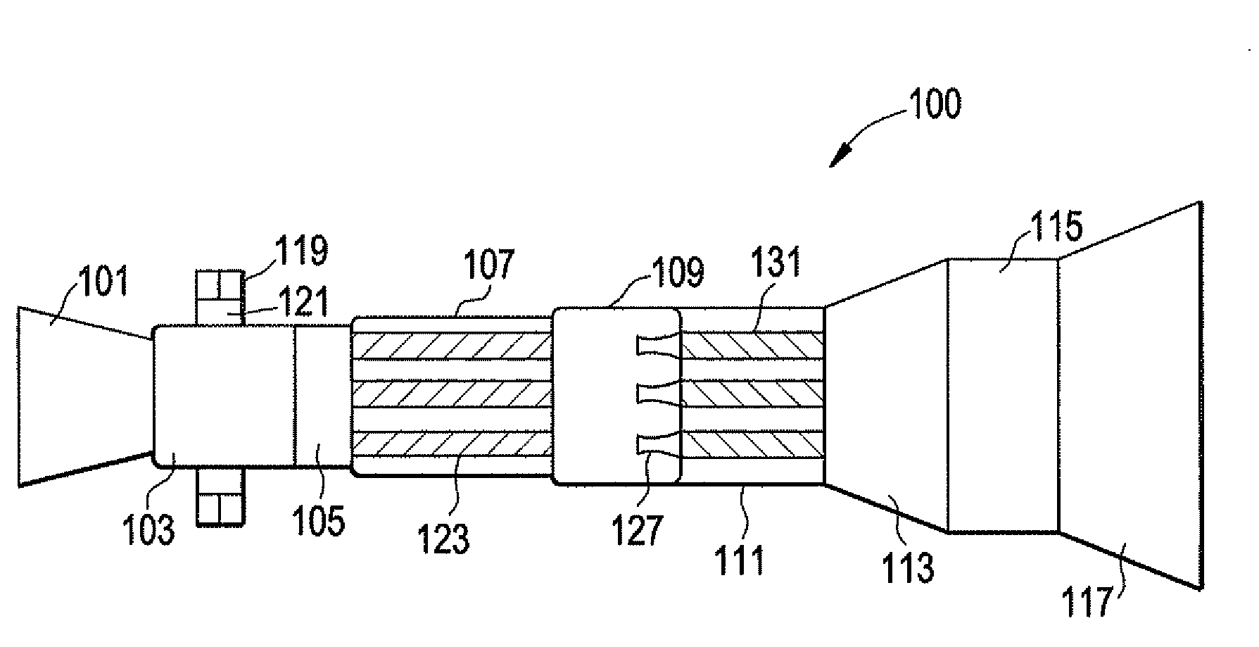
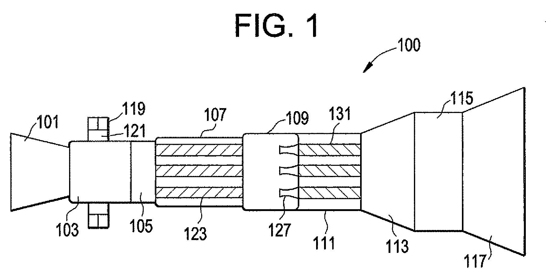
[0016]FIG. 1 depicts an engine 100 in accordance with an embodiment of the present invention. As shown, the engine 100 contains a compressor stage 101, a compressor plenum 103, PDC inlet valving 105, a PDC stage 107, a PDC exit nozzle stage 109, a transition stage 111, a high pressure turbine stage 113, a turbine plenum 115, and a low pressure turbine stage 117. It is noted that the compressor stage can be either a single or dual shaft type. Specifically, the compressor stage can have a high pressure and low pressure stage (similar to the turbine stage) such that the high pressure compressor stage is coupled to the high pressure turbine stage 113 and the low pressure compressor stage is coupled to the low pressure turbine stage 117.

[0017]The compressor stage 101 can be of any known configuration which can compress ...


PUM


Abstract

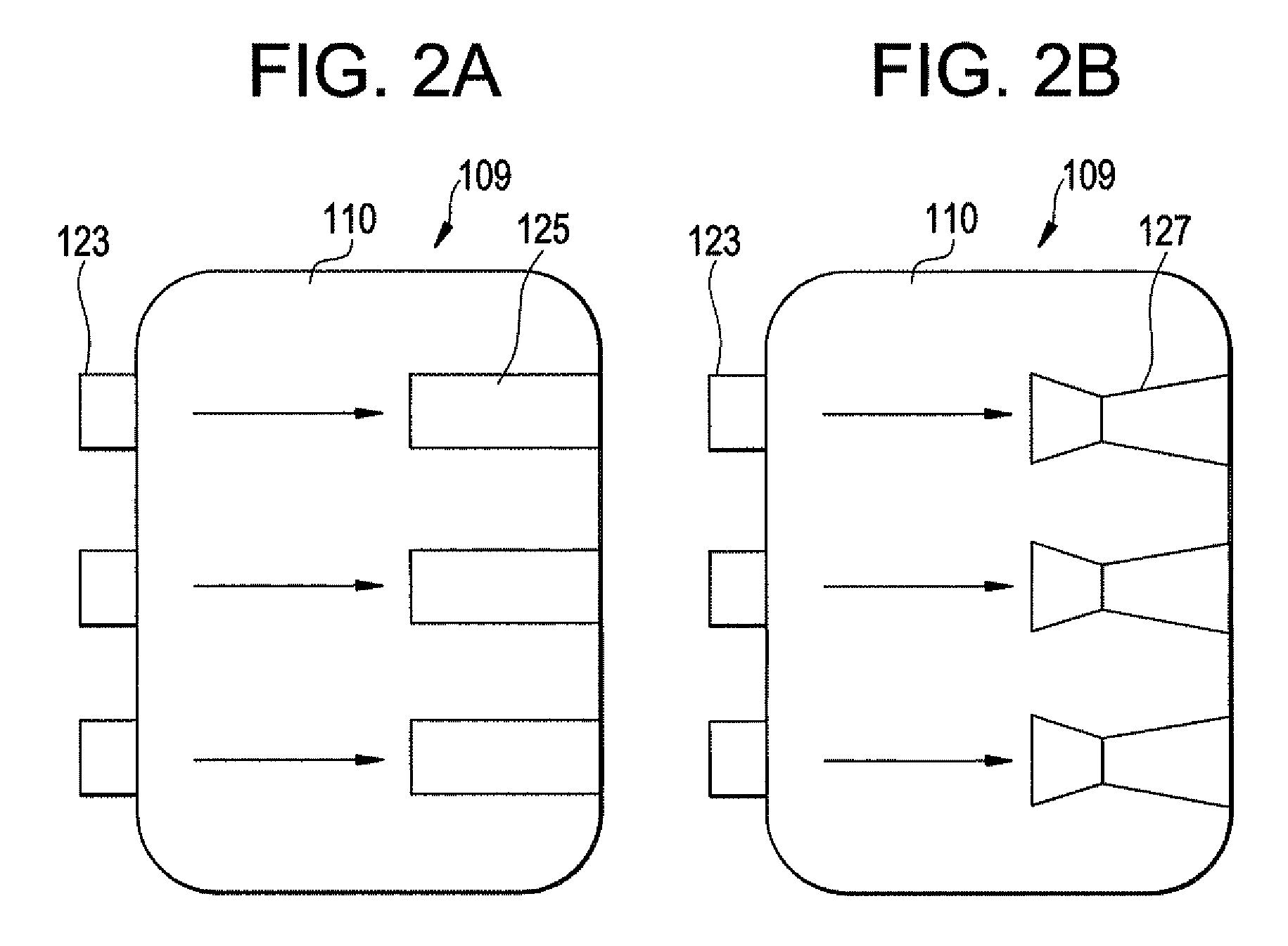
An engine contains a compressor stage, a compressor plenum, an inlet valving stage, a PDC stage, a PDC exit nozzle stage, a transition stage, a high pressure turbine stage, a turbine plenum, and a low pressure turbine stage. The PDC stage contains at least one pulse detonation combustor and each of the compressor plenum, PDC exit nozzle stage and turbine plenum contain a volume used to reduce and / or widen pressure peaks generated by the operation of the PDC stage.

Description

BACKGROUND OF THE INVENTION[0001]This invention relates to pulse detonation systems, and more particularly, to a ground-based simple cycle pulse detonation combustion engine for power generation.[0002]With the recent development of pulse detonation combustors (PDCs) and engines (PDEs), various efforts have been underway to use PDC / Es in practical applications, such as in aircraft engines and / or as means to generate additional thrust / propulsion, such as in ground based power generation systems. Further, there are efforts to employ PDC / E devices into “hybrid” type engines which use a combination of both conventional gas turbine engine technology and PDC / E technology in an effort to maximize operational efficiency. It is for either of these applications that the following discussion will be directed. It is noted that the following discussion will be directed to “pulse detonation combustors” (i.e. PDCs). However, the use of this term is intended to include pulse detonation engines, and ...

Claims


Application Information

Patent Timeline
Patent Type & Authority Patents(United States)
IPC IPC(8): F02K5/02
CPCF02C5/02F02K7/06F23R7/00F05D2220/62F05D2260/96
Inventor RASHEED, ADAMJOSHI, NARENDRA DIGAMBERTANGIRALA, VENKAT ESWARLU
Owner GENERAL ELECTRIC CO
Learn More