Buffer scheduling method for flow switching

a flow switching and buffer scheduling technology, applied in data switching networks, digital transmission, electromagnetic transceivers, etc., can solve the problems of not offering a solution to the particular requirements of optical buffers, unable to intelligently schedule traffic flows, etc., to improve the overall system switching throughput, save energy, and improve the effect of overall system switching efficiency

Active Publication Date: 2019-06-27
CHUNGHWA TELECOM CO LTD
View PDF2 Cites 9 Cited by
  • Summary
  • Abstract
  • Description
  • Claims
  • Application Information

AI Technical Summary

Benefits of technology

[0005]A buffer scheduling method is provided herein for a hybrid of an optical circuit switch and an electrical circuit switch on an Internet data center. When data is transmitted in a “Hybrid Switching Mode” using both the optical circuit switch and the electrical circuit switch on the Internet data centers or in an “All-optical Switching Mode” using only the optical circuit switch, the smart buffer scheduling method can be used to effectively improve the overall switch throughput.
[0015]In the all-optical switching field, a buffer scheduling method for a hybrid of an optical circuit switch and an electrical circuit switch is a revolutionary topic in the applications in Internet data centers (IDC). The buffer scheduling method according to the present invention improves the overall system switching throughput and also conserves more energy.
[0016]With the buffer scheduling method for a hybrid of optical circuit switches and electrical circuit switches in IDCs, regardless of whether flows are transmitted in the “Hybrid Switching Mode” or the “All-optical Switching Mode,” the smart buffer scheduling method according to the present invention can be used to effectively improve the overall switch throughput and switching efficiency and strengthen its architecture design.

Problems solved by technology

US 2014 / 0205292, titled “Optical Packet Switching System” originally assigned to Fujitsu Telecom Networks, proposes an optical buffer that adopts the configuration of a standard fiber delay line, which merely performs long optical delay times, but lacks a smart way of scheduling the traffic flows.
Neither does it offer a solution to the particular requirements of optical buffers on optical circuit switches.

Method used


Image

  • Buffer scheduling method for flow switching
  • Buffer scheduling method for flow switching
  • Buffer scheduling method for flow switching

Examples


Embodiment Construction

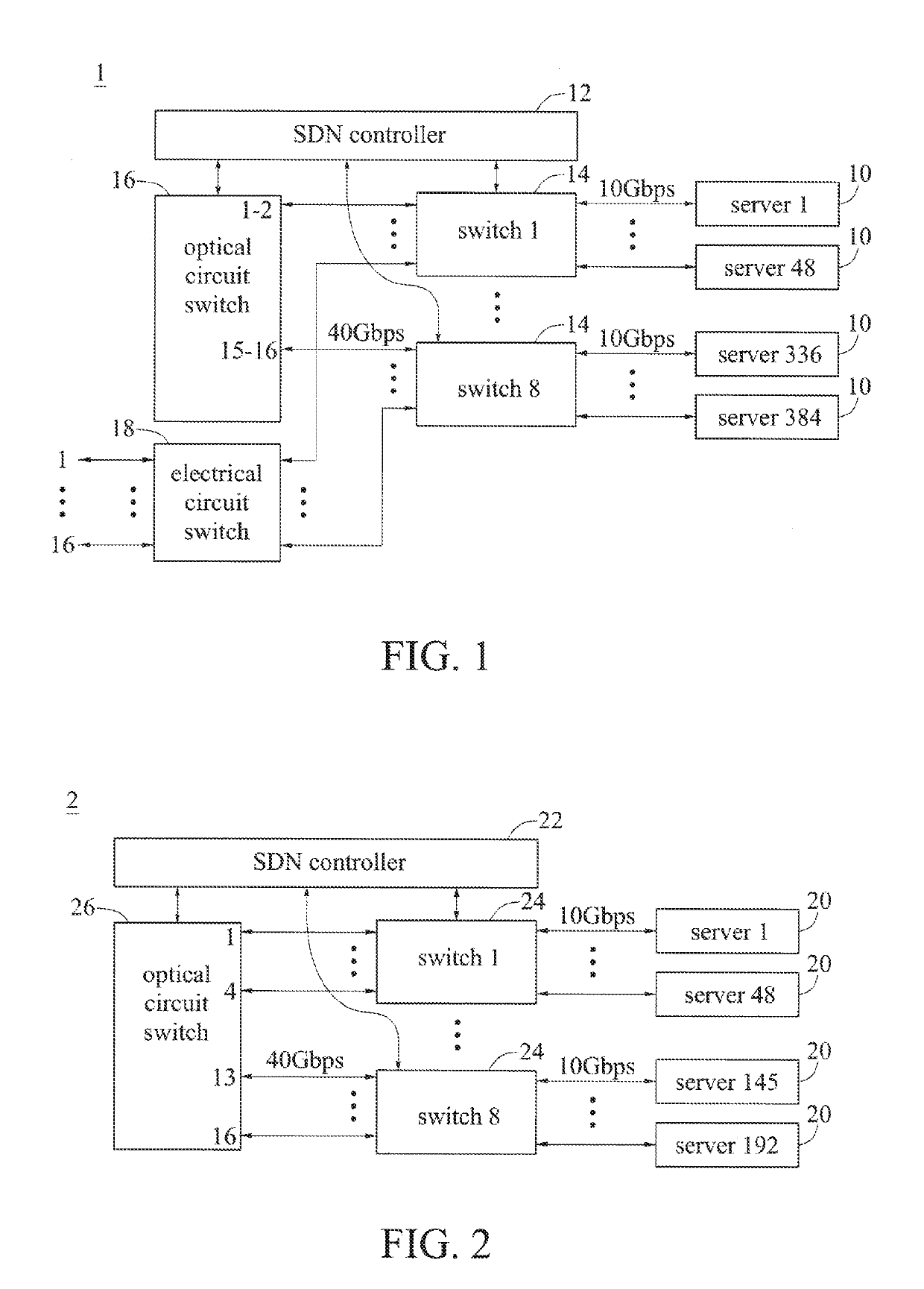
[0026]A buffer scheduling method is provided herein for a hybrid of an optical circuit switch and an electrical circuit switch on an Internet data center. When data is transmitted in a “Hybrid Switching Mode” using both the optical circuit switch and the electrical circuit switch on the Internet data centers or in an “All-optical Switching Mode” using only the optical circuit switch, the smart buffer scheduling method can be used to effectively improve the overall switch throughput.

[0027]As shown in FIG. 1, in a hybrid switching system 1 an offloading scheme is adopted. The hybrid switching system 1 includes servers 10, a SDN controller 12, switches 14 (such as aggregate switches), an optical circuit switch 16, and an electrical circuit switch 18. In an all-optical switching system 2, as shown in FIG. 2, a discard scheme, a padding scheme, a free-riding scheme, an aggregate scheme or a smart scheme can be used. The all-optical switching system 2 includes servers 20, a SDN controller...


PUM


Abstract

A buffer scheduling method is provided for use in an Internet data center in which flows are transmitted in a “Hybrid Switching Mode” using both an optical circuit switch and an electrical circuit switch or in an “All-optical Switching Mode” using only the optical circuit switch, to improve the overall switch throughput. In the “Hybrid Switching Mode,” an offloading scheme can be used; in the “All-optical Switching Mode,” a discard scheme, a padding scheme, a free-riding scheme, an aggregate scheme or a smart scheme can be used. During the transitioning stage of the technology, the offloading scheme can be used in the “Hybrid Switching Mode” to achieve significant improvement in the overall switching efficiency, whereas in the all-optical switching field, the free-riding scheme, the aggregate scheme and the smart scheme can be used to achieve good switching efficiency in the “All-optical Switching Mode.”

Description

BACKGROUND1. Technical Field[0001]The present invention relates to a buffer scheduling method for a hybrid of an optical circuit switch and an electrical circuit switch on an Internet data center.2. Description of Related Art[0002]TW Patent No. 1552536 (the counterpart of US 2016 / 0277816), titled “Optical Data Center Network System and Optical Switch,” describes an optical data center network system and an optical switch, wherein the optical switch is implemented using a commercially available Wavelength Selective Switch (WSS), and the optical data center network system is realized in three tiers, including multiple tier-1 optical switches, multiple tier-2 optical switches and multiple tier-3 optical switches. A pod is formed by the tier-1 optical switches connected to each other through ribbon fibers. A macro pod is formed by the tier-2 optical switches connected to each other through ribbon fibers, and each of the tier-2 optical switches is connected to all of the tier-1 optical s...

Claims


Application Information

Patent Timeline
Patent Type & Authority Applications(United States)
IPC IPC(8): H04Q11/00H04L12/46H04L12/863H04L12/859H04L12/813H04L12/805H04L47/20H04L47/2475H04L47/36
CPCH04Q11/0066H04L12/4641H04L47/6255H04L47/2475H04L47/20H04L47/36H04Q2213/05H04Q2011/0083H04L49/15H04Q11/0005H04Q2011/005H04L45/38H04L47/2441H04B10/40H04B10/50H04B10/60
Inventor CHENG, YUH-JIUHSHIAU, YHICHEN, BOR-TAUO
Owner CHUNGHWA TELECOM CO LTD
Why Eureka
Try Eureka