Electric power tool and motor control method thereof

a technology of electric power tools and motors, applied in the direction of power driven tools, portable percussive tools, wrenches, etc., can solve problems such as impact failures, and achieve the effects of reducing the rotation speed of the motor, suppressing the continuation of impact failures, and good operation efficiency

Active Publication Date: 2012-11-06
MAX CO LTD
View PDF15 Cites 18 Cited by
  • Summary
  • Abstract
  • Description
  • Claims
  • Application Information

AI Technical Summary

Benefits of technology

[0014]In the above electric power tool and its motor control method, an impact failure is determined based on the impact angle in one impact of the hydraulic pressure generator and the applied electric current proportional to the torque of the motor and the rotation speed of the motor is decreased when an impact failure is detected, so that a continuation of impact failure is suppressed. That is, according to the power electric tool and its motor control method of the embodiments of the invention, the impact failure is prevented as described above and thus an operation efficiency becomes good and a smooth fastening operation can be performed and the usability of the power electric tool becomes good.

Problems solved by technology

That is, in the tool of “two impact per one revolution”, an impact failure may occur because the impact frequency becomes high in a high load operation and responsibility of a hydraulic pressure generation mechanism worsens, etc.

Method used


Image

  • Electric power tool and motor control method thereof
  • Electric power tool and motor control method thereof
  • Electric power tool and motor control method thereof

Examples


first embodiment

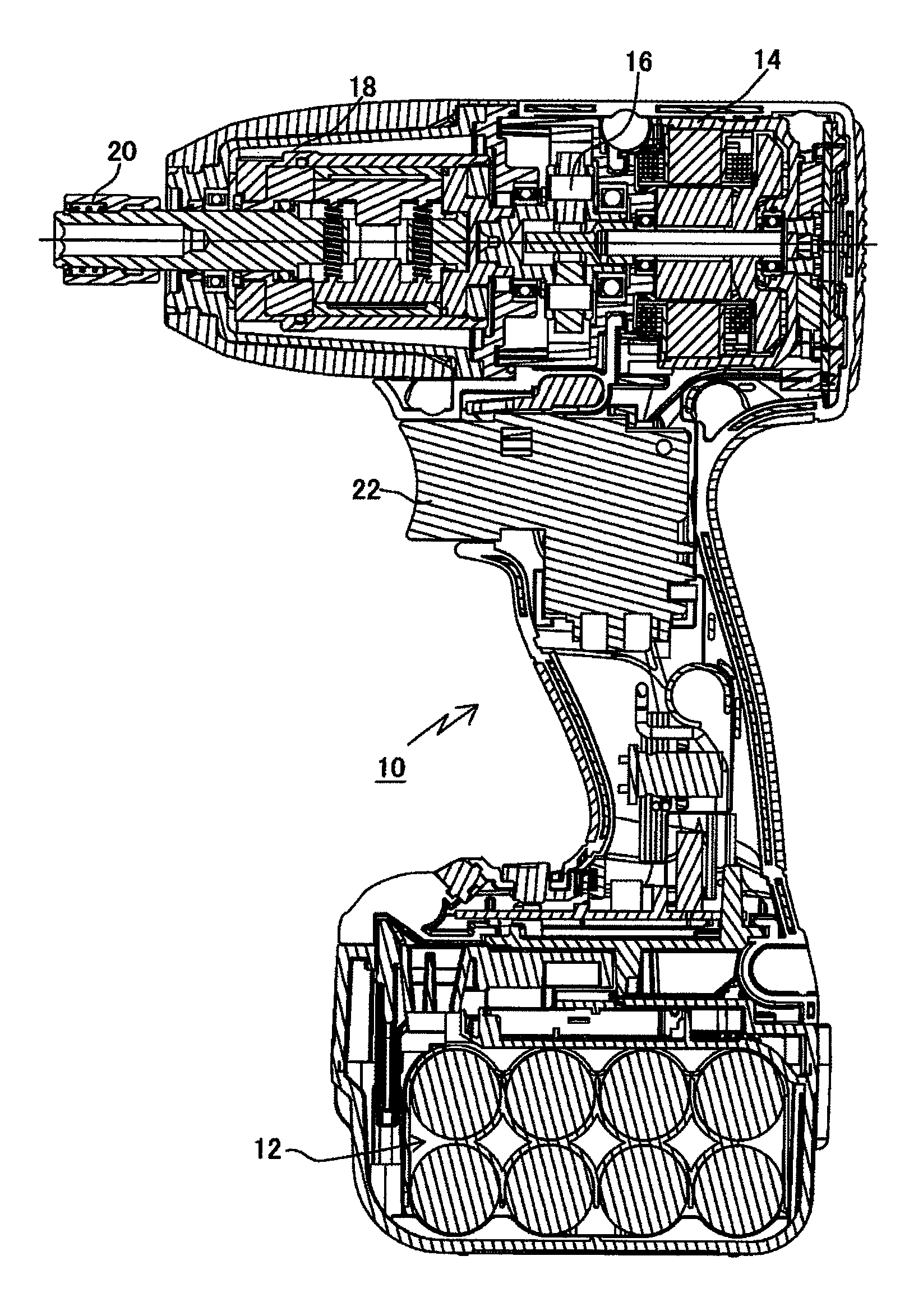
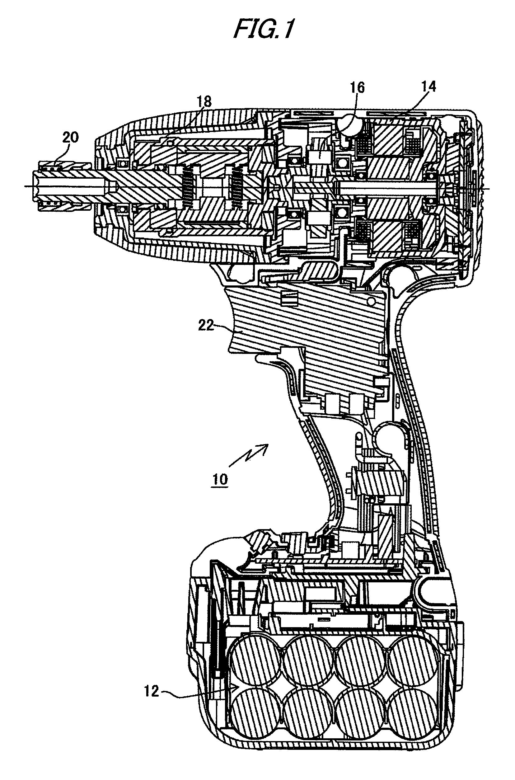
[0029]An electric power tool and its motor control method of a first embodiment of the invention is described based on an example of an oil pulse driver of multiple impacts per revolution (in the example, two impacts per revolution) shown in FIG. 1.

(Schematic Configuration of Oil Pulse Driver)

[0030]As shown in FIG. 1, an oil pulse driver 10 includes a battery 12 as a power supply, a brushless DC motor (which will be hereinafter also simply called motor) as a drive means, a speed reducer 16 for slowing down a rotation of the motor 14, a hydraulic pressure pulse generation mechanism 18 for receiving output of the speed reducer 16 and generating a hydraulic pressure pulse, a main shaft 20 to which a rotation impact force by the hydraulic pressure pulse generation mechanism 18 is transmitted, and a trigger lever 22. A driver bit (not shown) is attached to the main shaft 20. The battery 12 is placed detachably.

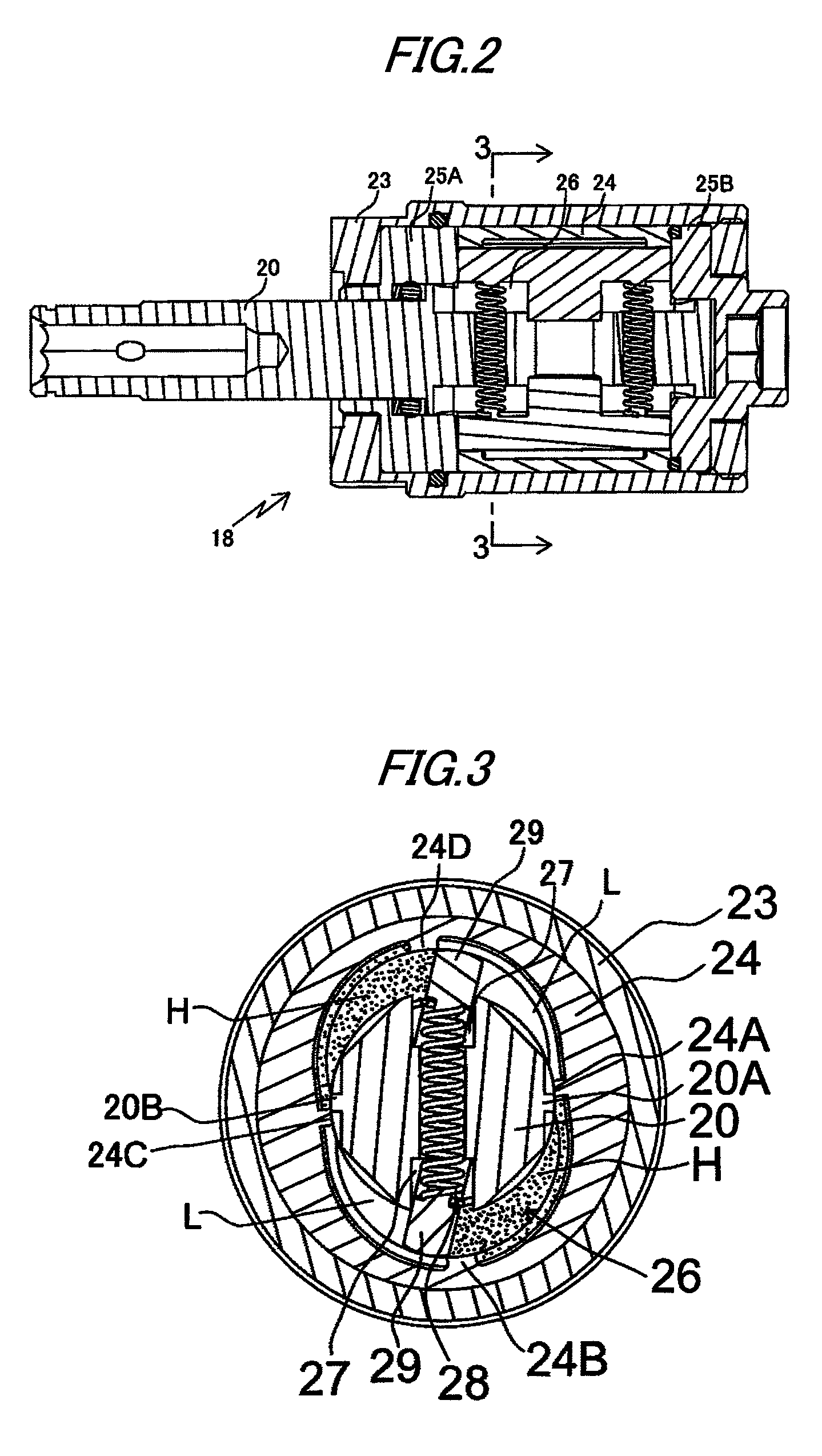
(Configuration Concerning Hydraulic Pressure Pulse Generation Mechanism)

[0031]...

embodiment

(Operation of Embodiment)

[0037]Processing concerning an impact control mode will be discussed based on a flowchart shown in FIG. 6. When the trigger lever 22 is pulled and a switch (not shown) is turned on, the CPU 30 loads a program, whereby processing in the oil pulse driver 10 is executed. The executed processing routine is represented by the flowchart of FIG. 6 and the programs are previously stored in the program area of the memory 32 (see FIG. 5). The routine is processing while the motor 14 (see FIG. 5) is rotating.

[0038]On the other hand, an impact failure can occur when the impact frequency is a given value or more, for example, 50 (times / s) or more. At this time, the angle advanced by one impact becomes small as compared with normal impact. That is, as shown in FIG. 9, when the angle advanced by one normal impact is small, the load on the motor is heavy and at the impact failure time, the load on the motor 14 is light although the impact angle is small.

[0039]Therefore, an ...

second embodiment

[0047]An electric power tool and its motor control method of a second embodiment of the invention will be discussed below with a block diagram of an oil pulse driver shown in FIG. 12: Parts identical with those of the first embodiment described above are denoted by the same reference numerals and will not be discussed again or is simplified and differences will be mainly discussed.

[0048]A CPU 40 of a rotation controller includes nonvolatile memory 42, an electric current detection section 44, and a rotating speed controller 46 and controls the whole operation of the oil pulse driver 10 shown in FIG. 1. The memory 42 of record means has a storage area for storing programs for controlling various types of processing and a record area for reading and writing various pieces of data and the impact angle, the threshold value data of consumption electric current, and the like are recorded in the record area.

[0049]As shown in FIG. 12, electric current Iad is input to the electric current de...


PUM


Abstract

An electric power tool is provided with: a motor; a hydraulic pressure generator driven by the motor and configured to generate a plurality of impacts in one revolution thereof; an impact angle detector configured to detect an impact angle in one impact of the hydraulic pressure generator; an electric current detector configured to detect an electric current applied to the motor; a determination unit configured to determine an impact failure based on the impact angle and the electric current detected by the impact angle detector and the electric current detector; and a rotation controller configured to decrease a rotation speed of the motor when the determination unit determines the impact failure.

Description

BACKGROUND OF THE INVENTION[0001]1. Field of the Invention[0002]This invention relates to an electric power tool in which a hydraulic pressure generator generates a plurality of impacts in one revolution thereof and a motor control method of the electric power tool.[0003]2. Background Art[0004]An electric power impact fastening tool as an electric power tool generally has a mechanism for generating one impact force per one revolution of a hydraulic pressure generator. (Refer to Patent Document 1.) In the electric power tool, a brushless DC motor is directly connected to an oil pulse unit to prevent occurrence of large vibration and reaction. (Refer to Patent Document 2.)[0005]On the other hand, as an impulse wrench which is a hydraulic pressure power tool, there is a tool in which two impact forces per one revolution of a hydraulic pressure generator driven by compressed air (which will be hereinafter also called “two impacts per one revolution”). (Refer to Patent Document 3.) The t...

Claims


Application Information

Patent Timeline
Patent Type & Authority Patents(United States)
IPC IPC(8): B25D11/00
CPCB25B21/02B25F5/005B25B23/1456
Inventor MORIMURA, KOUICHIROUAGEHARA, KIGEN
Owner MAX CO LTD
Why Eureka
Try Eureka