Optical disc drive

a technology of optical disc drives and optical disc drives, applied in the field of optical disc drives, can solve the problems of waveform degradation, waveform ringing and signal rise/fall time degradation, and the loss of high-speed reading bandwidth margins, so as to reduce the output impedance of a photodetector and reduce the characteristic impedance. , the effect of reducing the output impedan

Inactive Publication Date: 2012-11-06
HITACHI-LG DATA STORAGE +1
View PDF12 Cites 5 Cited by
  • Summary
  • Abstract
  • Description
  • Claims
  • Application Information

AI Technical Summary

Benefits of technology

[0018]With an optical disc drive according to an embodiment of the present invention, by dividing a differential transmission line, it is possible to adjust the characteristic impedance thereof. Specifically, it is possible to secure bandwidth by lowering the output impedance of a photodetector, while at the same time matching impedances by lowering the characteristic impedance of the differential transmission line in accordance with that output impedance. It is thus possible to realise high speed signal transmission while securing bandwidth for the photodetector.

Problems solved by technology

Due to bandwidth constraints of the optical pick up's photodetector itself, or to impedance mismatches between photodetectors and signal transmission lines, bandwidth margins for realizing high-speed reading have decreased for read signal transmission systems of optical disc drives.
When there are parts with impedance mismatches between the differential transmission line and elements located therebefore or thereafter, or within elements, multiple reflection of a signal occurs, which may cause waveform ringing and degradation in signal rise / fall time.
Consequently, at the input end of the differential transmission line, there arises a mismatch between the characteristic impedance of the differential transmission line and the output impedance of the OEIC, thereby causing waveform degradation as discussed above.

Method used


Image

  • Optical disc drive
  • Optical disc drive
  • Optical disc drive

Examples


embodiment 1

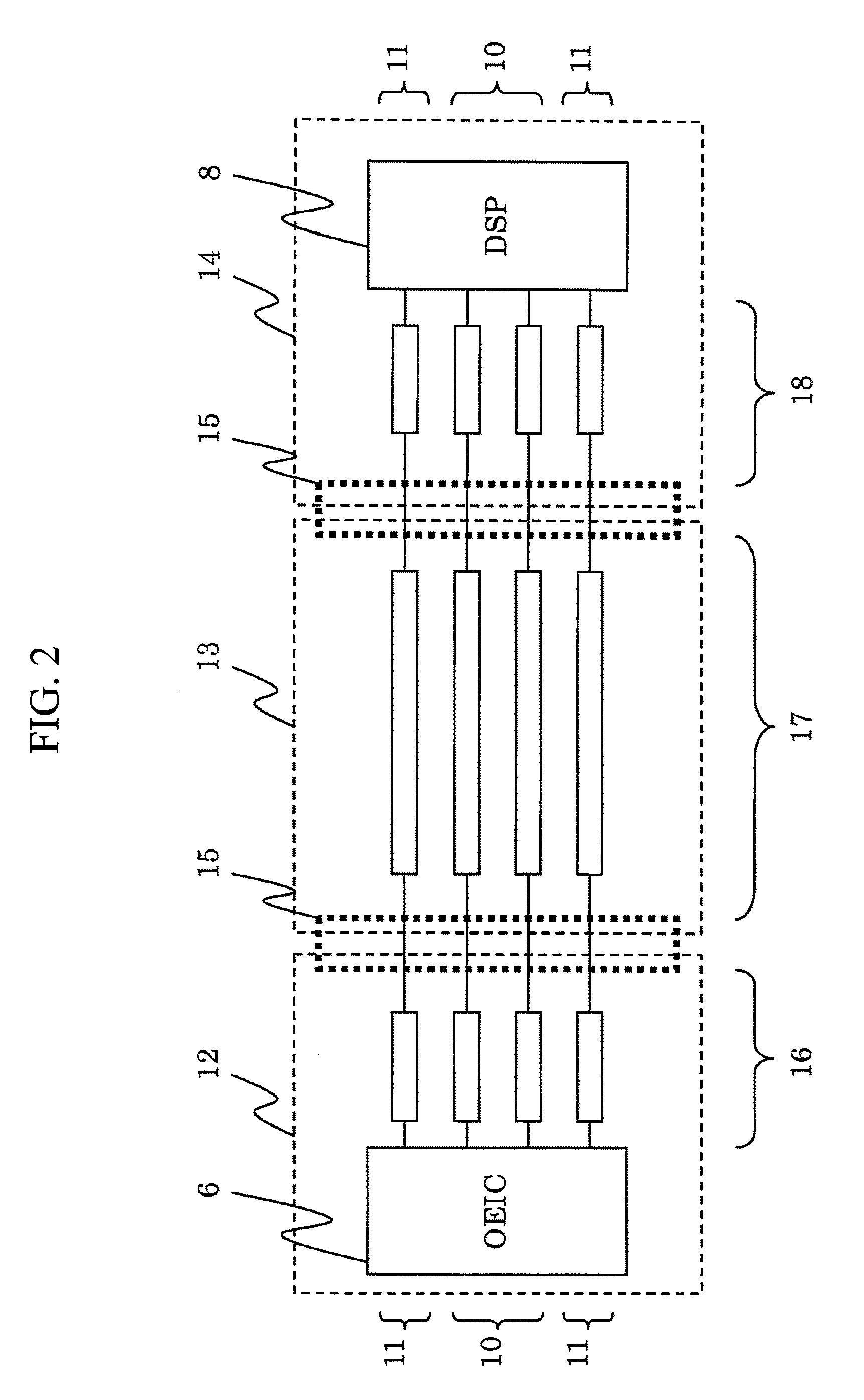
[0048]FIG. 3 is a configuration diagram of an optical disc drive according to Embodiment 1 of the present invention. Here, only the elements of a read signal transmission line that find correspondence in FIG. 2 are shown, and other general elements have been omitted.

[0049]In Embodiment 1, the two lines that form the differential transmission lines 10 are each further divided into two lines near the connection point between the first circuit board 12 and the flexible flat cable 13. Thus, at the lines 17 on the flexible flat cable 13, the differential transmission lines 10 are twice parallelized as compared to a conventional transmission line configuration. The divided lines are then re-integrated into one line near the connection point between the second circuit board 14 and the flexible flat cable 13.

[0050]With such a line configuration, as a result of the lines being parallelized at the section of the flexible flat cable 13 (i.e., at the lines 17), the inductance component of the d...

embodiment 2

[0051]FIG. 4 is a configuration diagram of an optical disc drive according to Embodiment 2 of the present invention. As in FIG. 3, only the elements of a read signal transmission line are shown, and other general elements have been omitted.

[0052]In Embodiment 2, the two lines forming the differential transmission lines 10 are each divided into two lines near the connection point between the first circuit board 12 and the flexible flat cable 13 as in Embodiment 1. Embodiment 2, however, differs from Embodiment 1 in that the lines are arranged in such a manner that lines that transmit antiphase differential signals are alternatingly adjacent to one another.

[0053]FIG. 5 is a diagram schematically showing an equivalent circuit for the line configuration shown in FIG. 4. For purposes of convenience, the circuit has been annotated with + and − signs to indicate the fact that the differential signals are of opposite phases.

[0054]As shown in FIGS. 4 and 5, when lines that transmit antiphase...

embodiments 1 and 2

Effects of Embodiments 1 and 2

[0055]Next, in order to confirm the effects of Embodiments 1 and 2, results of experiments independently conducted by the present inventors and of computer simulations are described. It is noted that the numerical values and elements indicated here are merely examples, and the present invention is not necessarily limited to these numerical values and elements.

[0056]FIG. 6 is a chart showing the results of evaluating the characteristic impedance of the flexible flat cable 13 (the lines 17) by itself. Here, flexible flat cables to be measured were connected to a coaxial cable 21 for measurement, and the characteristic impedance during differential transmission was evaluated using TDR (Time Domain Reflectometry). For purposes of comparison, the characteristic impedances of a conventional flexible flat cable and of the flexible flat cables 13 according to Embodiments 1 and 2 are presented alongside one another in FIG. 6.

[0057]In FIG. 6, the vertical axis re...


PUM

PropertyMeasurementUnit
output impedanceaaaaaaaaaa
lengthaaaaaaaaaa

Abstract

Bandwidth is secured for a read signal transmission line by matching the characteristic impedance of the read signal transmission line with the output impedance of a photodetector of an optical pick up, while at the same time securing bandwidth for the photodetector. In an optical disc drive according to an embodiment of the present invention, each line forming a differential transmission line is divided into a plurality of lines of the same quantity, the quantity being two or more, at or near a connection point between a flexible line and the optical pick up.

Description

CLAIM OF PRIORITY[0001]The present application claims priority from Japanese patent application JP 2010-186324 filed on Aug. 23, 2010, the content of which is hereby incorporated by reference into this application.BACKGROUND OF THE INVENTION[0002]1. Field of the Invention[0003]The present invention relates to optical disc drives.[0004]2. Background Art[0005]Capabilities to read and write signals faster with respect to large-capacity optical discs, as represented by Blu-ray (registered trademark) discs, are being demanded of today's optical disc drives. In order to read and write at high speeds, it is preferable that transmission lines be shortened to reduce transmission loss.[0006]On the other hand, flexible lines are used for a large part of read / write signal transmission lines in optical disc drives in order to make the optical pick up movable. Consequently, due to a need to secure a given range of motion, transmission lines physically require a certain length. In addition, flexib...

Claims


Application Information

Patent Timeline
Patent Type & Authority Patents(United States)
IPC IPC(8): G11B7/00
CPCG11B7/13G11B7/005
Inventor KITAYAMA, AKIRAKAKU, TOSHIMITSUNISHIMURA, HAJIME
Owner HITACHI-LG DATA STORAGE
Why Eureka
Try Eureka