Relay device, relay method, and optical communication system which uses relay device
a relay device and relay technology, applied in the field of relay devices, relay methods, optical communication systems which use relay devices, can solve the problems of poor signal quality, and achieve the effects of extending the transmission distance, increasing the number of splits, and securing bandwidth per user
- Summary
- Abstract
- Description
- Claims
- Application Information
AI Technical Summary
Benefits of technology
Problems solved by technology
Method used
Image
Examples
first embodiment
Connection Mode of an Optical Communication System
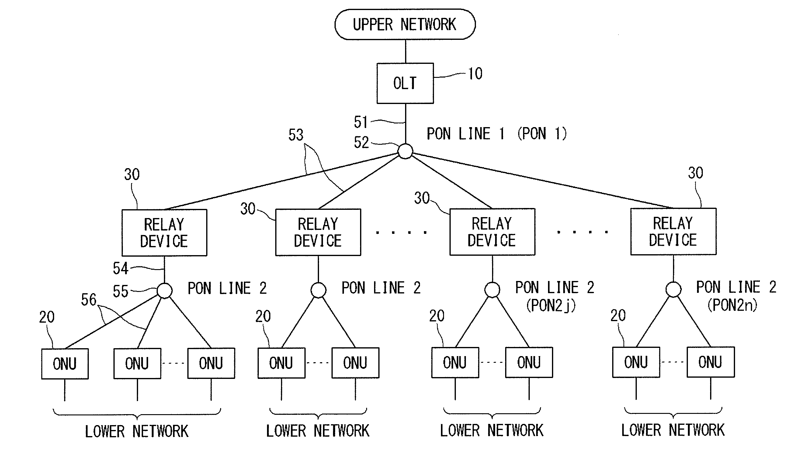
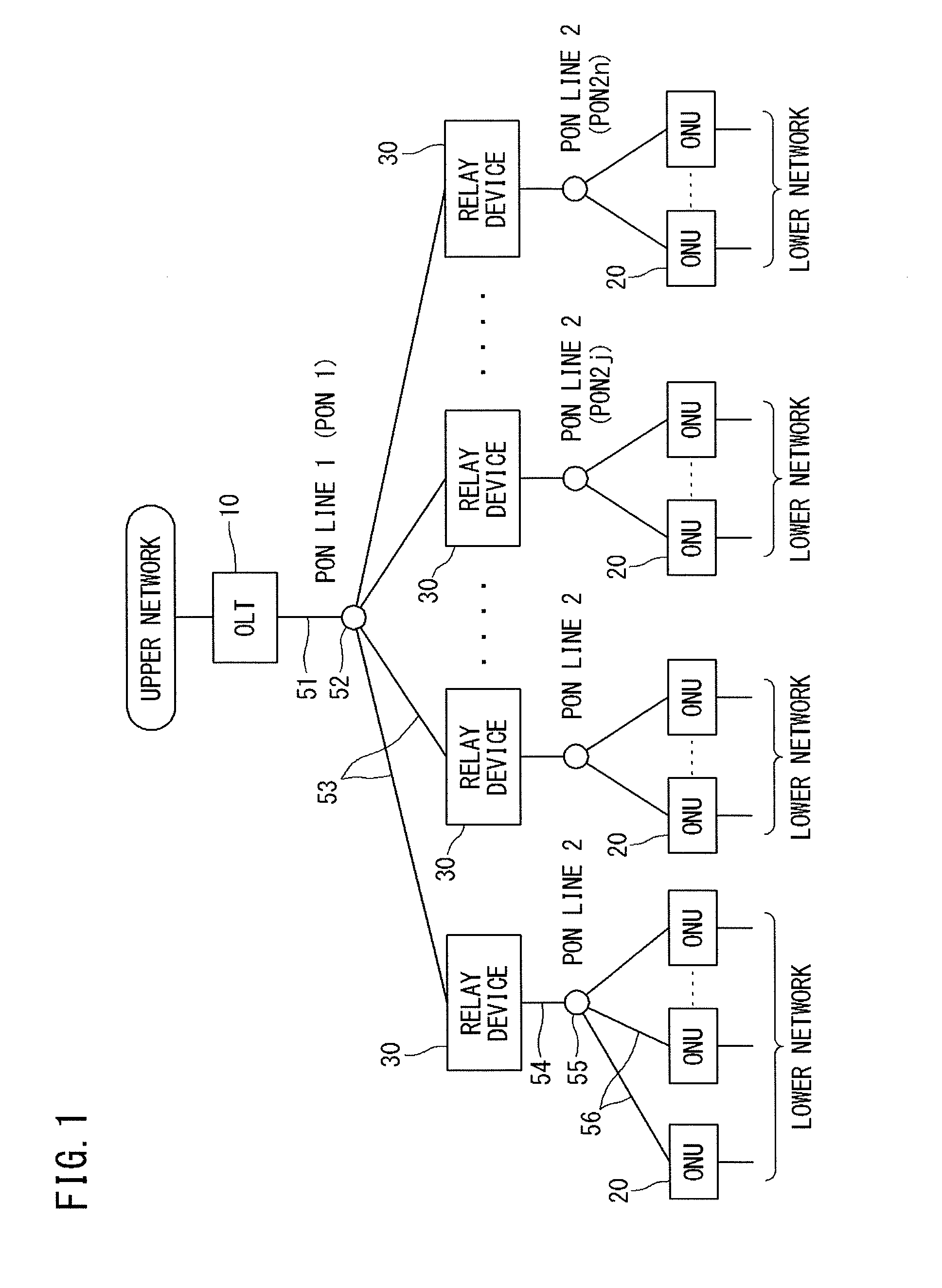
[0092]FIG. 1 is a diagram showing a connection mode of an optical communication system according to a first embodiment of the present invention.
[0093]As shown in FIG. 1, the optical communication system of the present embodiment has a connection mode (topology) in which one station side device 10 and multiple home side devices 20 are connected to each other with a plurality of relay devices 30 therebetween serving as intermediaries and by PON lines 1 and 2 at upper and lower levels.
[0094]Specifically, the one station side device 10 is connected to the plurality of relay devices 30 under the control thereof by optical fibers in a P2MP manner. Each relay device 30 is connected to a plurality of home side devices 20 under the control thereof by optical fibers in a P2MP manner.
[0095]More specifically, a single-core optical fiber 51 connected to the station side device 10 is split into a plurality of single-core optical fibers 53 through ...
second embodiment
Device Configuration, Etc., of the Second Embodiment
[0211]The configurations of an optical communication system, an OLT 10, and ONUs 20 according to a second embodiment of the present invention are the same as those in the case of the first embodiment (see FIGS. 1 to 3).
[0212]Meanwhile, a relay device 30 used in the second embodiment acts as a plurality of “logical ONUs” with respect to an upper-level PON 1. The logical ONUs are provided so as to have a one-to-one correspondence with ONUs 20 in a lower-level PON 2j (j=1, 2 . . . n).
[0213]The basic components of the relay device 30 are the same as those in the case of the first embodiment (FIG. 4). However, in the second embodiment, a second upstream buffer 40 for upstream user frames is provided for each logical ONU in the upper-level PON.
[0214]Upon relaying an upstream user frame, the relay device 30 of the second embodiment uniquely determines an LLID to be used in the PON 1 which is a relay destination, from an LLID used in the P...
third embodiment
Device Configuration, Etc., of the Third Embodiment
[0278]The configurations of an optical communication system, an OLT 10, ONUs 20, and relay devices 30 according to a third embodiment of the present invention are the same as those in the case of the first embodiment (see FIGS. 1 to 4).
[0279]In addition, a registration sequence, a multiple access sequence, and a removal sequence are the same as those in the case of the first embodiment (see FIGS. 5 and 6).
[0280]However, in the third embodiment, a PON transmitting and receiving unit 21 of an ONU 20 (see FIG. 3) has a “sleep function” that stops an upstream transmission function. If a sleep signal inputted from a control unit 24 is enabled, the PON transmitting and receiving unit 21 stops a transmission function by turning off the power to its laser diode and transmitter circuit, thereby reducing power consumption.
[0281]Likewise, a transmission processing unit 22 of the ONU 20 (see FIG. 3) also has a “sleep function”. If a sleep signa...
PUM
 Abstract
Description
Claims
Application Information
 - R&D
- Intellectual Property
- Life Sciences
- Materials
- Tech Scout
- Unparalleled Data Quality
- Higher Quality Content
- 60% Fewer Hallucinations
Browse by: Latest US Patents, China's latest patents, Technical Efficacy Thesaurus, Application Domain, Technology Topic, Popular Technical Reports.
© 2025 PatSnap. All rights reserved.Legal|Privacy policy|Modern Slavery Act Transparency Statement|Sitemap|About US| Contact US: help@patsnap.com


