Relay device, relay method, and optical communication system which uses relay device

a relay device and relay technology, applied in multiplex communication, data switching details, high-level techniques, etc., can solve problems such as poor signal quality, and achieve the effects of extending transmission distance, ensuring bandwidth per user, and increasing the number of splits

Active Publication Date: 2016-05-24
SUMITOMO ELECTRIC IND LTD
View PDF32 Cites 1 Cited by
  • Summary
  • Abstract
  • Description
  • Claims
  • Application Information

AI Technical Summary

Benefits of technology

[0075]As described above, according to the present invention, an optical communication system capable of economically extending the transmission distance can be formed. In addition, according to the present invention, an optical communication system capable of increasing the number of splits while securing bandwidth per user can be formed.
[0076]Furthermore, according to the present invention, when sleep control is performed in an optical communication system having an upper-level PON and lower-level PONs, a delay in the resumption of traffic can be prevented.

Problems solved by technology

In such a PON system, the larger the number of splits and the transmission distance, the poorer the signal quality.

Method used


Image

  • Relay device, relay method, and optical communication system which uses relay device
  • Relay device, relay method, and optical communication system which uses relay device
  • Relay device, relay method, and optical communication system which uses relay device

Examples


first embodiment

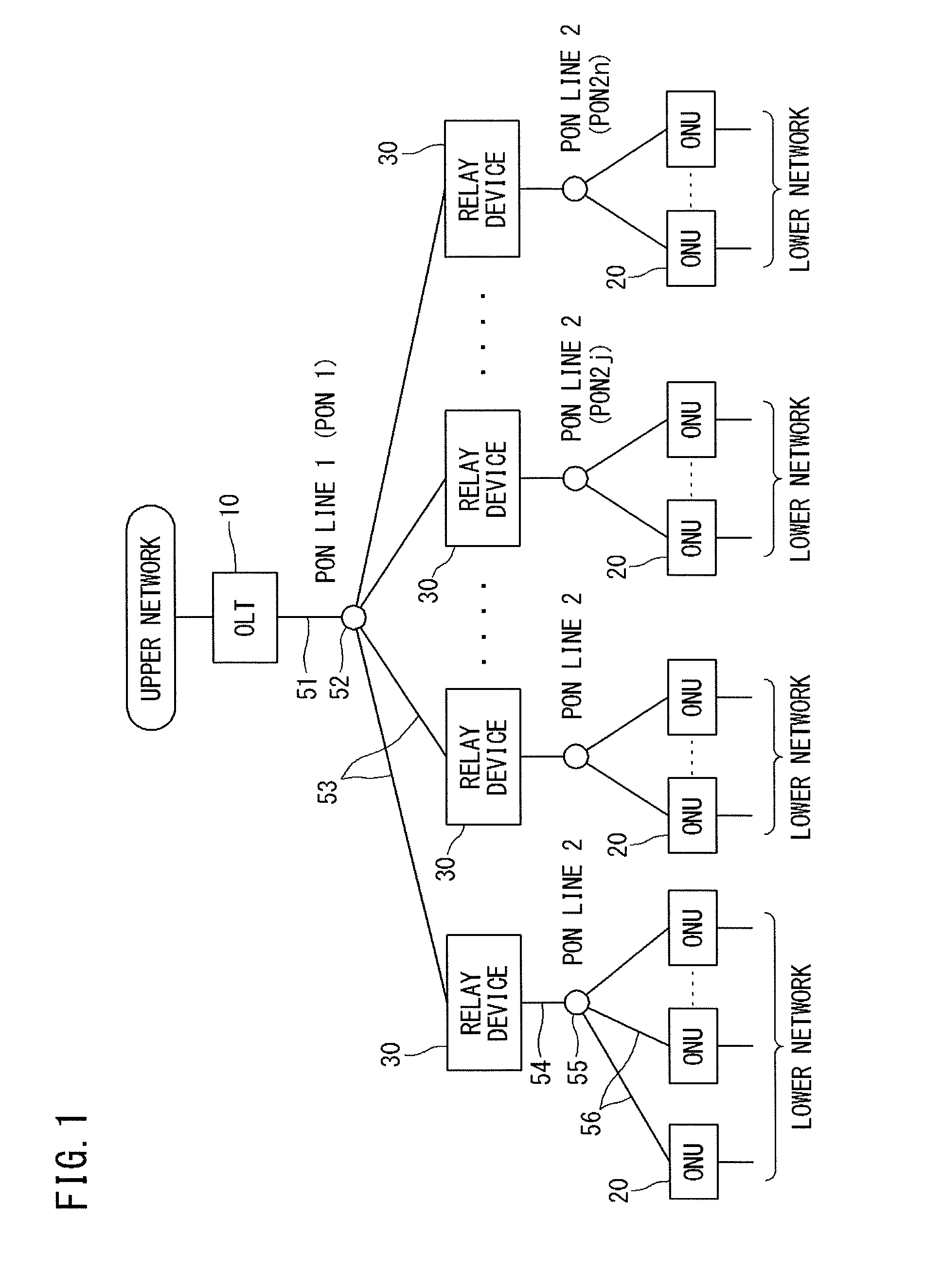
[0092][Connection mode of an optical communication system]

[0093]FIG. 1 is a diagram showing a connection mode of an optical communication system according to a first embodiment of the present invention.

[0094]As shown in FIG. 1, the optical communication system of the present embodiment has a connection mode (topology) in which one station side device 10 and multiple home side devices 20 are connected to each other with a plurality of relay devices 30 therebetween serving as intermediaries and by PON lines 1 and 2 at upper and lower levels.

[0095]Specifically, the one station side device 10 is connected to the plurality of relay devices 30 under the control thereof by optical fibers in a P2MP manner. Each relay device 30 is connected to a plurality of home side devices 20 under the control thereof by optical fibers in a P2MP manner.

[0096]More specifically, a single-core optical fiber 51 connected to the station side device 10 is split into a plurality of single-core optical fibers 53 ...

second embodiment

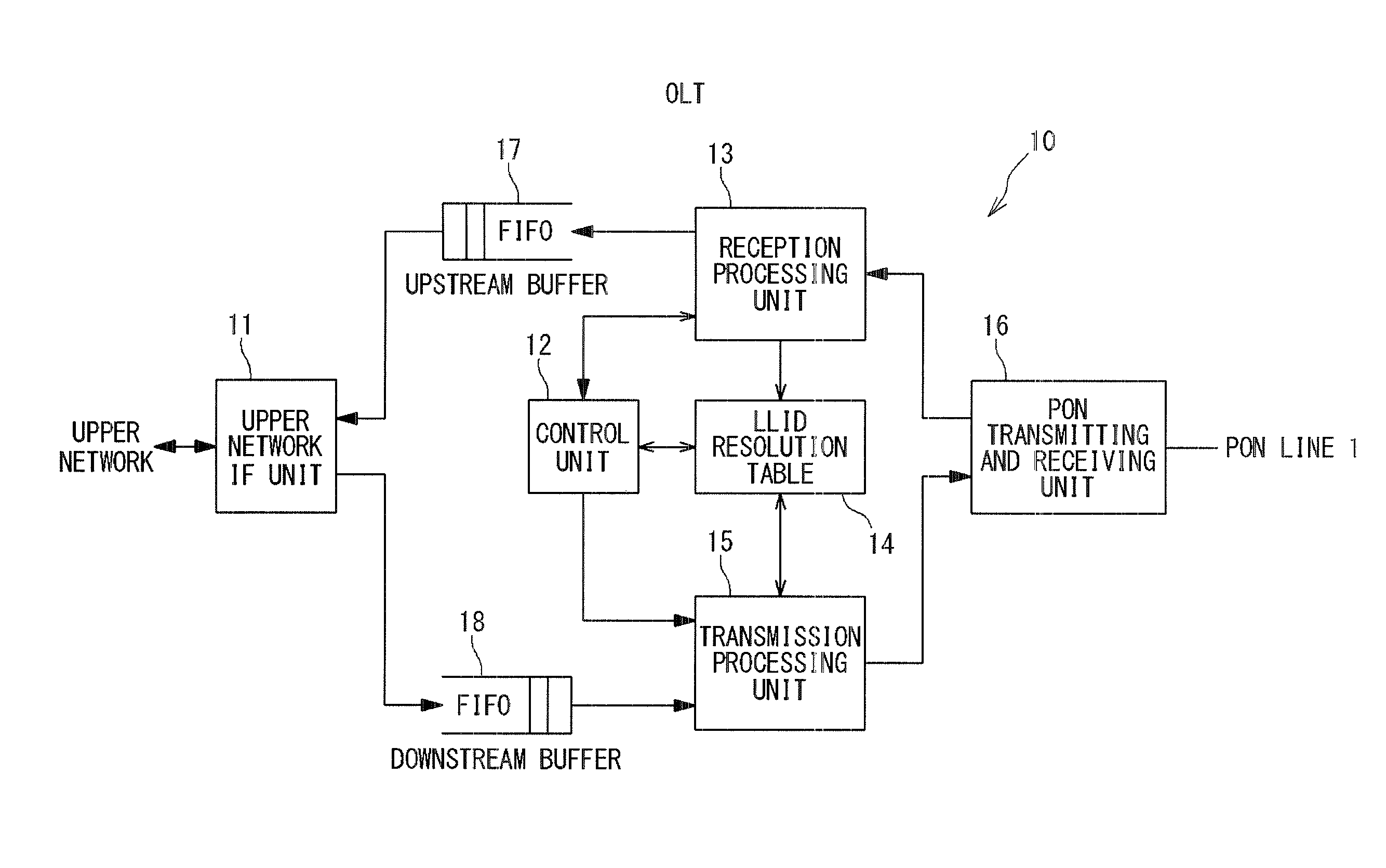
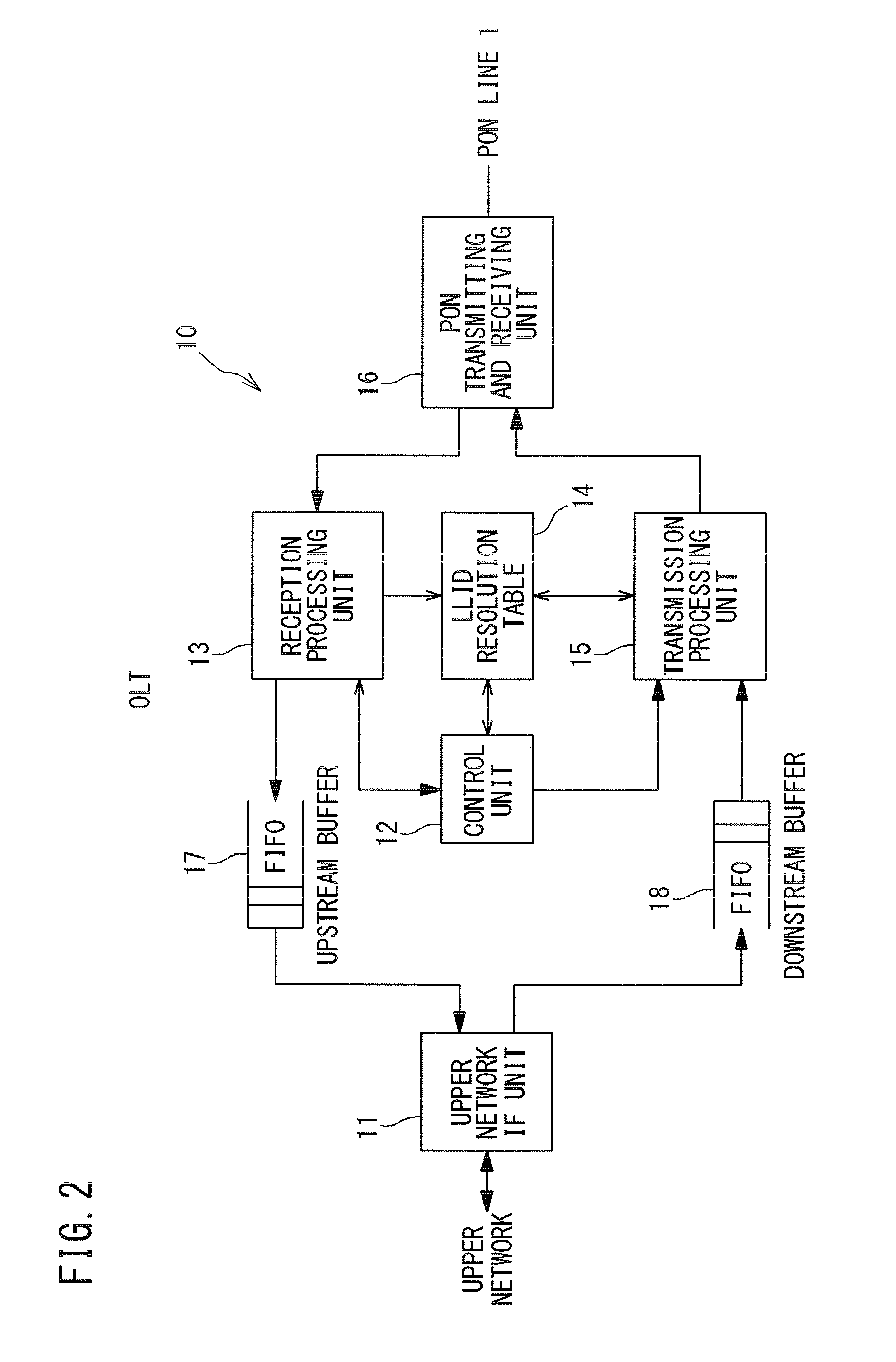
[0212][Device configuration, etc., of the second embodiment]

[0213]The configurations of an optical communication system, an OLT 10, and ONUs 20 according to a second embodiment of the present invention are the same as those in the case of the first embodiment (see FIGS. 1 to 3).

[0214]Meanwhile, a relay device 30 used in the second embodiment acts as a plurality of “logical ONUs” with respect to an upper-level PON 1. The logical ONUs are provided so as to have a one-to-one correspondence with ONUs 20 in a lower-level PON 2j (j=1, 2 . . . n).

[0215]The basic components of the relay device 30 are the same as those in the case of the first embodiment (FIG. 4). However, in the second embodiment, a second upstream buffer 40 for upstream user frames is provided for each logical ONU in the upper-level PON.

[0216]Upon relaying an upstream user frame, the relay device 30 of the second embodiment uniquely determines an LLID to be used in the PON 1 which is a relay destination, from an LLID used ...

third embodiment

[0280][Device configuration, etc., of the third embodiment]

[0281]The configurations of an optical communication system, an OLT 10, ONUs 20, and relay devices 30 according to a third embodiment of the present invention are the same as those in the case of the first embodiment (see FIGS. 1 to 4).

[0282]In addition, a registration sequence, a multiple access sequence, and a removal sequence are the same as those in the case of the first embodiment (see FIGS. 5 and 6).

[0283]However, in the third embodiment, a PON transmitting and receiving unit 21 of an ONU 20 (see FIG. 3) has a “sleep function” that stops an upstream transmission function. If a sleep signal inputted from a control unit 24 is enabled, the PON transmitting and receiving unit 21 stops a transmission function by turning off the power to its laser diode and transmitter circuit, thereby reducing power consumption.

[0284]Likewise, a transmission processing unit 22 of the ONU 20 (see FIG. 3) also has a “sleep function”. If a sle...


PUM


Abstract

A relay device includes a first transmitting and receiving unit connected to a PON line on the upper-level side and performing mutual conversion between optical and electrical signals; a second transmitting and receiving unit connected to a PON line on the lower-level side and performing mutual conversion between optical and electrical signals; a relay processing unit relaying a downstream frame received by the first unit to the second unit, and relays an upstream frame received by the second unit to the first unit; and a control unit. The control unit follows upstream multiple access control performed by a station side device, for transmission of the upstream frame to be transmitted by the first unit to the station side device, and independently performs upstream multiple access control for reception of the upstream frame received by the second unit from a home side device.

Description

TECHNICAL FIELD[0001]The present invention relates to a relay device and a relay method for extending the transmission distance between a station side device and home side devices which form a PON (Passive Optical Network) system, and an optical communication system using the relay device.BACKGROUND ART[0002]A PON system is an optical communication system that performs optical splitting in a P2MP (Point to Multi Point) connection mode, with no power and includes a station side device; a single-core optical fiber network where an optical fiber connected to the station side device is split into a plurality of optical fibers through an optical coupler; and home side devices connected to ends of the split optical fibers, respectively.[0003]In the PON system, NRZ (Non-Return to Zero) optical signals obtained by directly or externally modulating a light source such as a semiconductor laser are transmitted, by which information is sent and received.[0004]A downstream optical signal sent fr...

Claims


Application Information

Patent Timeline
Patent Type & Authority Patents(United States)
IPC IPC(8): H04J14/02H04L12/44H04J14/00H04B10/27H04L12/12
CPCH04J14/0221H04B10/27H04L12/12H04L12/44Y02B60/32Y02B60/34Y02D30/50H04B10/0775
Inventor YAMASHITA, KAZUHISA
Owner SUMITOMO ELECTRIC IND LTD
Why Eureka
Try Eureka