Device and method for determining the aperture angle of a joint

a technology of aperture angle and joint, which is applied in the field of devices and methods for determining the aperture angle of joints, can solve the problems of short service life of hip joint implants, excessive wear and tear, and surgeons can only very roughly assess whether flexibility ascertained and assessed in this way is sufficient, so as to improve the effect of verifying and assessing and improving the outcome of implantation

Inactive Publication Date: 2012-11-13
SMITH & NEPHEW ASIA PACIFIC PTE LTD +2
View PDF8 Cites 14 Cited by
  • Summary
  • Abstract
  • Description
  • Claims
  • Application Information

AI Technical Summary

Benefits of technology

[0007]It is an object of the present invention to propose a device and a method for determining the aperture angle of a joint, which can be used to precisely verify whether implant components are correctly seated.
[0010]The device in accordance with the invention thus enables an improvement in verifying and assessing, and, therefore, in performing, the implantation of an artificial joint, such that the outcome of implantation can be improved. Positional values and angular values can be automatically ascertained, in order, for example, to verify that a joint is correctly seated using movements performed manually or automatically, for example, using robots. Taking into account anatomically relevant influencing parameters, such as the ligaments, soft tissues, etc., it can be ascertained whether movements, which may be performed using the implanted joint, are sufficient or whether the implant or the seating of the implant still has to be changed, in order to obtain the desired range of motion of the joint. A joint can, for example, be moved in each direction until it is no longer possible, using normal force, to open or close the joint further due to it colliding with a body structure or a component of the joint or due to other factors, such that the range of motion of the joint can be ascertained in various directions. Precise angular values can be ascertained by the device in accordance with the invention, which can be compared, for example, with predetermined reference values, to verify the correct seating or the correct functionality of a joint, without being reliant on the experience of a surgeon.

Problems solved by technology

Even the smallest deviations can lead to excessively rapid wear and tear and, therefore, to a short service life of the hip joint implant.
However, a surgeon can only very roughly assess whether flexibility ascertained and assessed in this way is sufficient for the patient's daily life.

Method used


Image

  • Device and method for determining the aperture angle of a joint
  • Device and method for determining the aperture angle of a joint
  • Device and method for determining the aperture angle of a joint

Examples


Embodiment Construction

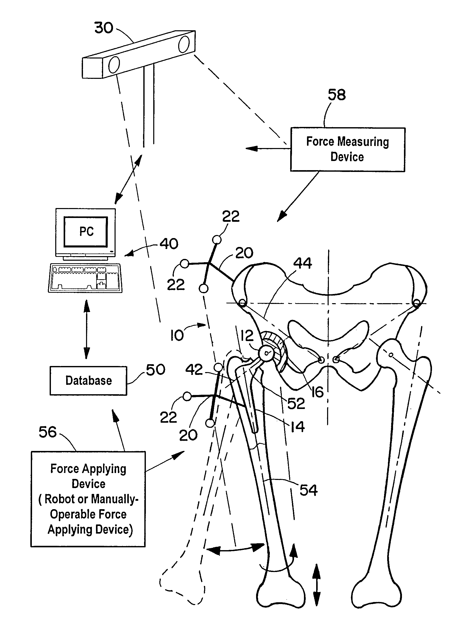
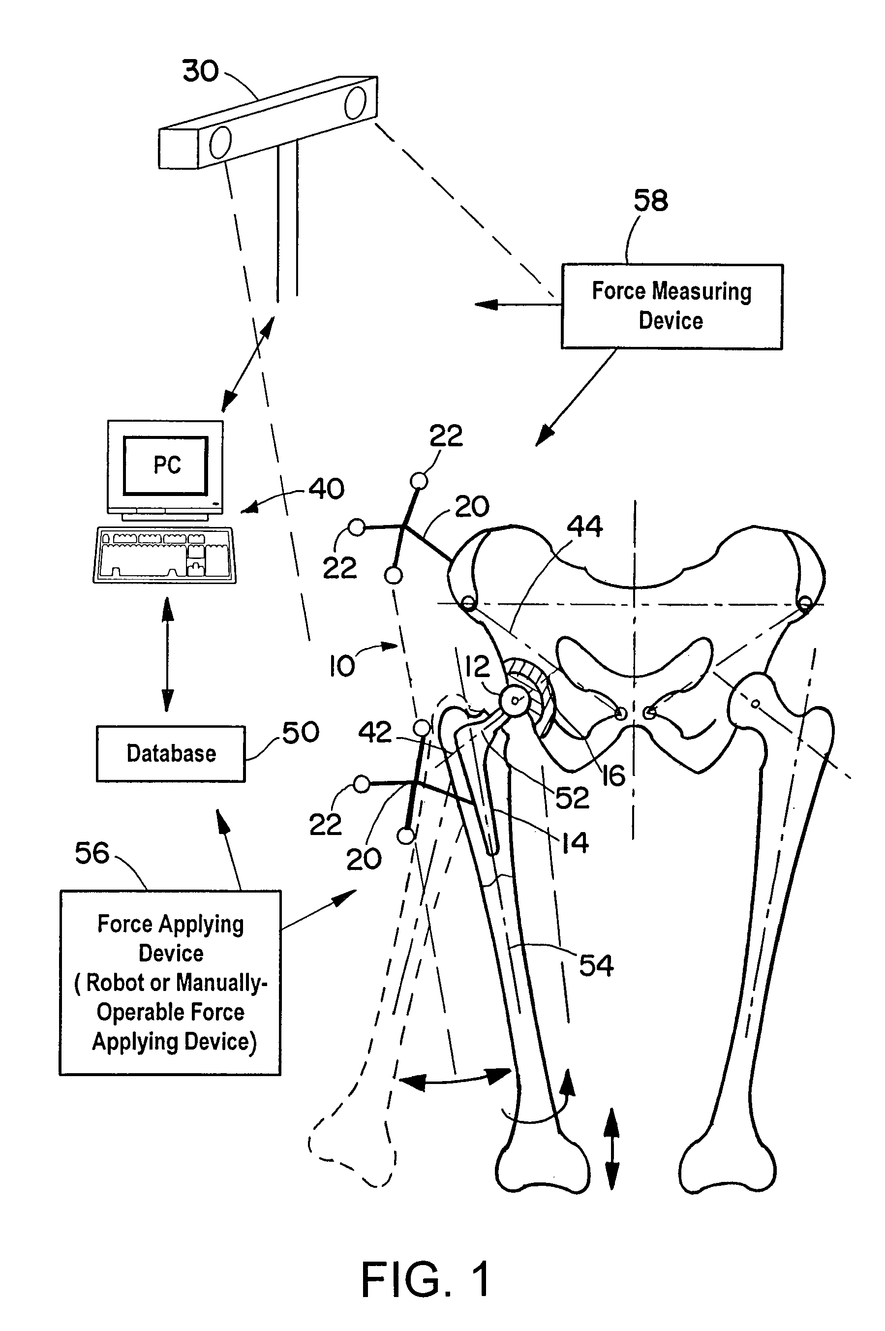
[0027]The invention relates to a device and method for determining an aperture angle of a joint lying between two body structures, such as, for example, the aperture angle of a hip joint, a knee joint, an elbow joint or other joints. It is to be appreciated that the term “aperture angle” is intended to be understood, for example, in the case of the ball joint-like hip joint, both as the angle between a fixed upper leg axis and a plane or axis defined by the position of the hip, and as the spatial position or orientation of the angle. The intention is, for example, to ascertain how far the femur is inclined forwards, backwards or to the side, relative for example to the hip, i.e. the spatial angle which the joint forms is determined. The intention is also, for example, to ascertain how a joint or parts or structures thereof are rotated, for example, about a center axis.

[0028]FIG. 1 schematically shows an artificial hip joint 10 including a joint head 12 of a femur implant 14, which i...


PUM


Abstract

A device for determining the aperture angle of a joint includes a detection device for detecting positions of joint components and / or positions of structures connected to or to be connected to the joint and a computational unit for ascertaining the aperture angle of the joint based on the detected positions.

Description

RELATED APPLICATION DATA[0001]This application is a continuation of U.S. application Ser. No. 10 / 670,177, filed on Sep. 23, 2003 now abandoned, which claims priority to U.S. Provisional Application No. 60 / 440,700, filed on Jan. 17, 2003, both of which are incorporated herein by reference in their entireties.FIELD OF THE INVENTION[0002]The present invention relates to a device and a method for determining the aperture angle of a joint lying between two body structures.BACKGROUND OF THE INVENTION[0003]Artificial hip joints are known in which a femur implant is introduced into a bodily femur, after a head of the bodily joint has been removed. A joint cavity is introduced into the hip as a counter bearing, which, as an abutment, can accommodate a spherical or partially spherical head of the femur implant. Seating the implants precisely is a fundamental criterion for successfully implanting a hip joint. Even the smallest deviations can lead to excessively rapid wear and tear and, therefo...

Claims


Application Information

Patent Timeline
Patent Type & Authority Patents(United States)
IPC IPC(8): A61B5/103A61B5/117A61B19/00A61F2/32A61F2/34A61F2/36A61F2/46
CPCA61B19/46A61B19/5244A61F2/4657A61B5/064A61B5/1121A61B5/4851A61B5/72A61B19/2203A61B2019/464A61B2019/467A61B2019/502A61B2019/505A61B2019/5255A61B2019/5272A61B2019/566A61F2/32A61F2/34A61F2/36A61F2002/3611A61F2002/4632A61F2002/4658A61F2002/4666A61F2002/4668A61F2002/4697A61B2034/102A61B2034/2055A61B2034/2072A61B2034/256A61B34/20A61B2090/064A61B2090/067A61B34/30A61B90/06A61B2034/105A61F2002/4696
Inventor TUMA, GREGORSCHUBERT, MARIOSHAFFRATH, CLAUS
Owner SMITH & NEPHEW ASIA PACIFIC PTE LTD
Why Eureka
Try Eureka