Method and apparatus for performing coordinated multi-PTZ camera tracking

a multi-ptz, camera technology, applied in direction finders, instruments, television systems, etc., can solve the problems of affecting the ability of the response team, unable to provide visual feedback, and finite time delay between

Active Publication Date: 2012-11-13
SRI INTERNATIONAL
View PDF1 Cites 33 Cited by
  • Summary
  • Abstract
  • Description
  • Claims
  • Application Information

AI Technical Summary

Problems solved by technology

Radar, fence, acoustics and seismic sensors provide the first line of threat detection capability, but do not provide visual feedback.
There is a finite time delay between an intrusion, dispatch of a response team, and eventual interception of the intruder.
This time delay introduces ambiguity in the location of the intruder, which essentially impacts the ability of the response team to quickly intercept the intruder.
Even though a single PTZ can pan all around (360 degrees), large areas of interests may get occluded due to buildings, trees and the like.
As a result, an object being tracked may temporarily—or even permanently—get lost during a period where there is an occlusion.

Method used


Image

  • Method and apparatus for performing coordinated multi-PTZ camera tracking
  • Method and apparatus for performing coordinated multi-PTZ camera tracking
  • Method and apparatus for performing coordinated multi-PTZ camera tracking

Examples


Embodiment Construction

[0019]Embodiments of the present invention provide at least the following capabilities: 1) active collaborative tracking of multiple targets over a wide area; 2) Passive tracking based on external 2D / 3D track data; 3) Visual assessment; 4) Video & track based object designation; 5) Output 2D and 3D tracks for all observed objects.

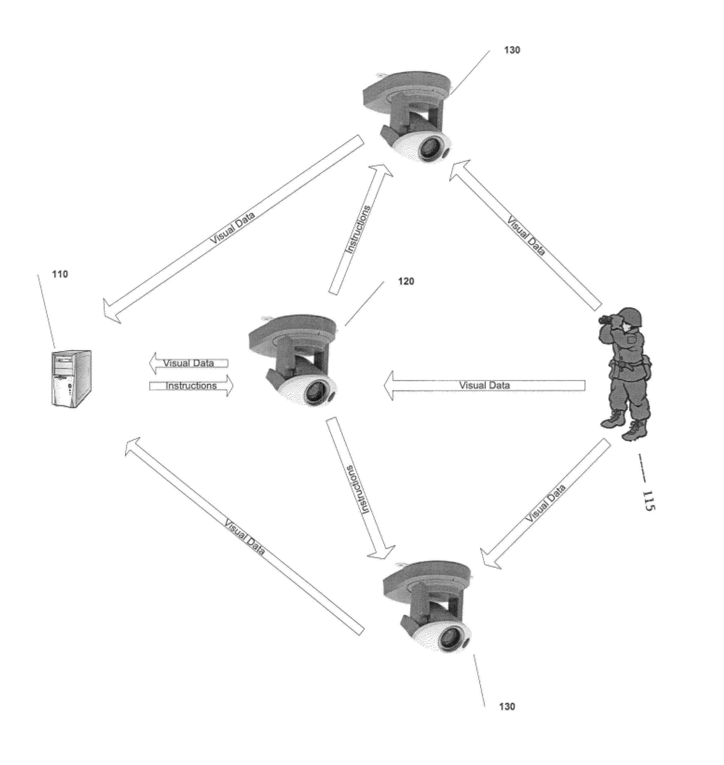
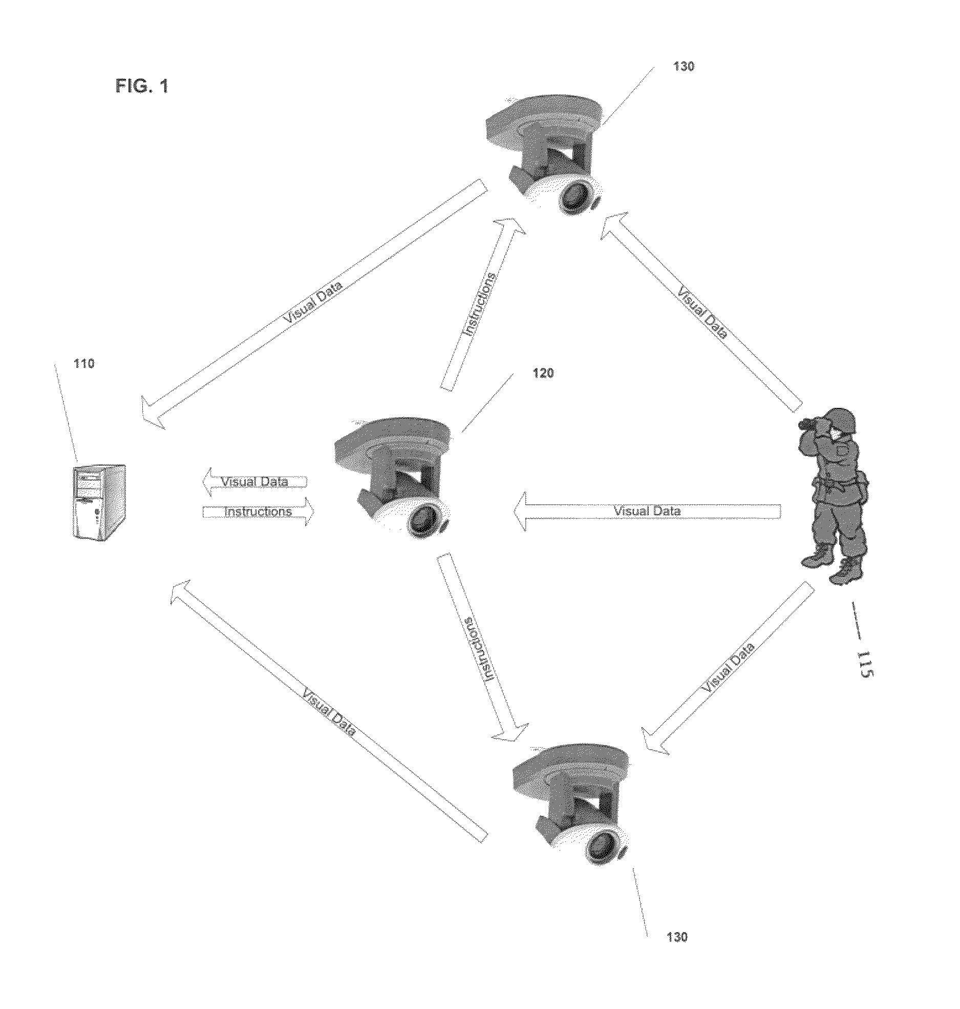
[0020]With reference to FIG. 1, a system for monitoring a field of view is depicted. The system according to embodiments of the present invention includes manager component 110 which is capable of receiving visual data regarding an at least one object to be tracked and sending at least one control signal to a series of visual sensing units to track the at least one object 115. The system according to embodiments of the present invention also includes visual sensing unit in a master mode 120 associated with the manager component 110 and capable of receiving visual data, transmitting the visual data to the manager component 110 regarding the position of the a...


PUM


Abstract

A system for tracking at least one object is disclosed. The system includes a plurality of communicatively connected visual sensing units configured to capture visual data related to the at least one object The system also includes a manager component communicatively connected to the plurality of visual sensing units. The manager component is configured to assign one visual sensing unit to act as a visual sensing unit in a master mode and at least one visual sensing unit to act as a visual sensing unit in a slave mode. The manager component is further configured to transmit at least one control signal to the plurality of visual sensing units, and receive the visual data from the plurality of visual sensing units.

Description

CROSS-REFERENCE TO RELATED APPLICATION[0001]This application claims the benefit of U.S. Provisional Application 60 / 718,637, filed Sep. 20, 2005. The entire disclosure of U.S. Provisional Application Ser. No. 60 / 718,637 is hereby incorporated herein by reference.FIELD OF THE INVENTION[0002]Embodiments of the present invention generally relate to video surveillance methods and systems and in particular to a method and apparatus for coordinating pan, tilt and zoom (PTZ) cameras to track activities where the field of view of certain of the PTZ cameras may include occlusions.BACKGROUND OF THE INVENTION[0003]A key need for border security is the ability for rapid visual assessment, verification, classification, and continuous tracking and localization of possibly multiple simultaneous threats, detected by wide area sensors such as radar, fence sensor, and local sensors (e.g., acoustics and under-ground seismic sensors).[0004]Radar, fence, acoustics and seismic sensors provide the first li...

Claims


Application Information

Patent Timeline
Patent Type & Authority Patents(United States)
IPC IPC(8): H04N5/232
CPCG01S3/7864H04N7/181
Inventor AGGARWAL, MANOJSETHI, DEEPAKSAMARASEKERA, SUPUNPARAGANO, VINCE
Owner SRI INTERNATIONAL
Why Eureka
Try Eureka