Signal processing apparatus, signal processing method, and program for signal processing

a signal processing and signal processing technology, applied in the direction of color signal processing circuits, instruments, television systems, etc., can solve the problem of small edge enhancement effect to steepen the rise portion of the step waveform, and achieve the effect of improving the apparent resolution of the up-converted signal and steepening the signal change for the edge portion

Active Publication Date: 2012-11-13
PANASONIC CORP
View PDF36 Cites 2 Cited by
  • Summary
  • Abstract
  • Description
  • Claims
  • Application Information

AI Technical Summary

Benefits of technology

[0014]In view of the problem described above, an object of the present invention is to provide a signal processing apparatus, a signal processing method, and a signal processing program capable of causing no overshoot to occur in the edge portion of an image having a step waveform upon up-conversion to improve sharpness.
[0018]In this aspect, the absolute value of the gradient of the signal change can be increased by shifting the phase of the signal for the edge portion upon up-conversion. As a result, the signal change for the edge portion is steepened, and the apparent resolution of the up-converted signal can be improved over the related art. Also, since no high-frequency filter is used for the phase shifting process to steepen the signal change, the waveform distortion which otherwise might be caused by the overshoot is advantageously avoided.

Problems solved by technology

Also, the problem is posed that the edge enhancement effect to steepen the rise portion of the step waveform is small.

Method used


Image

  • Signal processing apparatus, signal processing method, and program for signal processing
  • Signal processing apparatus, signal processing method, and program for signal processing
  • Signal processing apparatus, signal processing method, and program for signal processing

Examples


first embodiment

1. Configuration

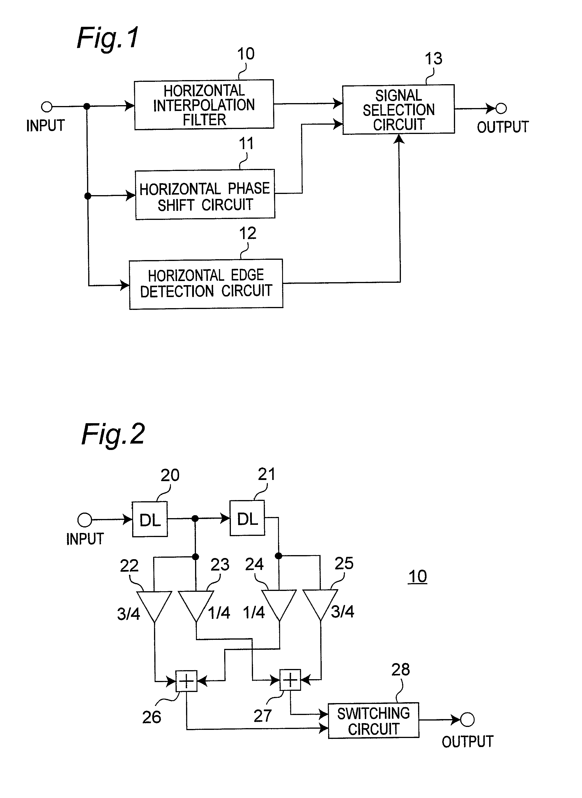
[0036]FIG. 1 is a block diagram showing a configuration of a signal processing apparatus according to a first embodiment. According to this embodiment, the signal processing apparatus is described, which doubles the number of pixels in a horizontal direction of an input image. This signal processing apparatus includes a horizontal interpolation filter 10, a horizontal phase shift circuit 11, a horizontal edge detection circuit 12 and a signal selection circuit 13. The pixel value of each of pixels composing the image to be converted is input from the input terminal in the order of raster scan at intervals of a predetermined sampling period. Specifically, the pixels are input in such a manner that the lines composing the image are scanned downward from the top and from left to right. In the following description, it is assumed that an input image having 720 effective pixels in the horizontal direction for a total of 858 pixels including the horizontal blanking part an...

second embodiment

[0059]FIG. 7 is a block diagram showing the configuration of the signal processing apparatus according to a second embodiment. The description of the first embodiment describes the signal processing apparatus which doubles the number of pixels of the input image in the horizontal direction. On the other hand, in the signal processing apparatus according to the second embodiment doubles the number of pixels of the input image in a vertical direction. The basic concept of this embodiment is similar to that of the first embodiment.

[0060]Like in the first embodiment, the pixel value of each of pixels composing the image to be converted is input from the input terminal in the order of raster scan at a predetermined sampling period. As in the first embodiment, it is assumed that the input image having a total of 858 pixels (720 effective pixels) in the horizontal direction and a total of 525 lines (480 effective lines) in the vertical direction is progressively scanned by an image signal ...

third embodiment

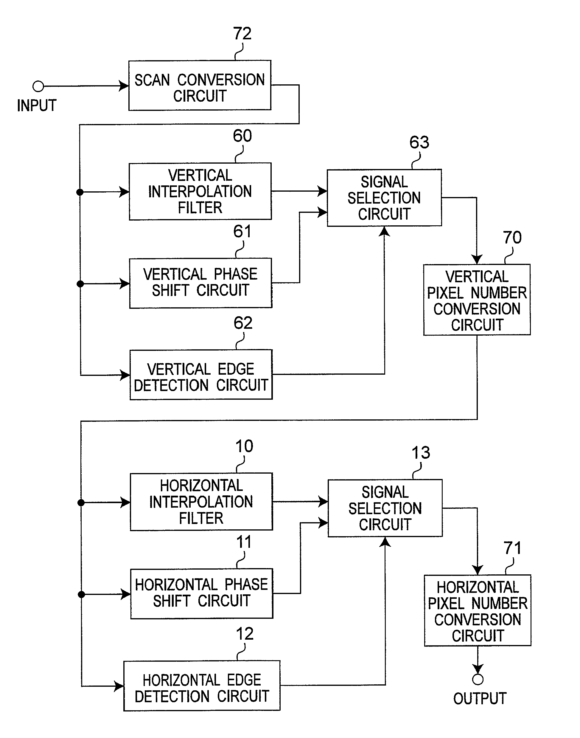
[0074]FIG. 8 is a block diagram showing a configuration of a signal processing apparatus according to a third embodiment. The signal processing apparatus according to this embodiment is a serial combination of the signal processing apparatus according to the second embodiment shown in FIG. 7 and the signal processing apparatus according to the first embodiment shown in FIG. 1. In FIG. 8, the same component elements as those of the first and second embodiments are designated by the same reference numerals, respectively, and not described in detail.

[0075]In the signal processing apparatus according to the third embodiment configured as described above, the vertical interpolation filter 60, the vertical phase shift circuit 61, the vertical edge detection circuit 62 and the signal selection circuit 63 generate image signals of ¼ phase and ¾ phase between two vertically adjacent original pixels of the input image signal, and double the number of pixels in the vertical direction. As descr...


PUM


Abstract

A signal processing circuit includes an interpolation filter for outputting an interpolation value of signal levels at positions of ¼ phase and ¾ phase between two original pixels of the input digital image adjacent in the predetermine direction; a phase shift circuit for outputting signal value of each of the two original pixels by shifting the phases of the signals of the two original pixels in the predetermined direction to ¼ phase and ¾ phase, respectively, between the two original pixels; a edge detection circuit for detecting a edge portion of the image from a signal level change of a plurality of pixels including the two original pixels of the input digital image in the predetermined direction; and a first signal selection circuit for outputting the output of the phase shift circuit when the edge is detected, and outputting the output of the interpolation filter when no edge is detected, based on the result of detection by the edge detection circuit.

Description

BACKGROUND ART[0001]1. Technical Field[0002]The technical field relates to a signal processing apparatus, a signal processing method, and a signal processing program for converting an original image to an image having a larger number of pixels.[0003]2. Related Art[0004]In a conventional up-converting technique for converting an original image to an image of a higher definition, i.e. an image having a larger number of pixels, the number of pixels is increased by interpolating the pixels of the original image thus generating new pixels. In the process, various signal processing operations such as an edge-enhancement process are performed to improve the sharpness of the image. A signal processing apparatus of this type is described in, for example, JP-A-2005-354161. FIG. 13 is a block diagram showing a configuration of a conventional signal processing apparatus described in JP-A-2005-354161. With reference to FIG. 13, the interpolation process for the conventional up-converting method ...

Claims


Application Information

Patent Timeline
Patent Type & Authority Patents(United States)
IPC IPC(8): H04N7/01G06K9/32G06K9/40G06K9/48H04N11/20H04N9/74H04N5/00H04N5/21
CPCG06T3/4007G06T3/403H04N7/0142
Inventor WADA, NORIAKI
Owner PANASONIC CORP
Why Eureka
Try Eureka