System and method for visualizing needle entry into a body

a system and needle technology, applied in the field of system and method for visualizing the needle, can solve the problems of inability to visualize the blood vessel under normal conditions, delay in placing the intravenous line, and inability to perform venipuncture, which is often the rate-limiting step in administering intravenous compounds, etc., to achieve the effect of more rapid and accurate performan

Active Publication Date: 2012-11-13
BECTON DICKINSON & CO
View PDF8 Cites 4 Cited by
  • Summary
  • Abstract
  • Description
  • Claims
  • Application Information

AI Technical Summary

Benefits of technology

[0015]Thus, implementations of the present systems enable a medical clinician to visualize not only internal anatomical structures, but also a needle as it is advanced into a body. As clinicians are enabled to visualize internal structures, venipuncture procedures may be performed more rapidly and accurately.

Problems solved by technology

Venipuncture, which is often the rate-limiting step when administering intravenous compounds, can take as long as a half hour, or longer when the patient is a neonate, infant, geriatric, obese, or burn patient.
Notwithstanding the enormous financial burden on our society as a whole because operating rooms and health-care providers must wait as an intravenous line is placed, the delay in placing an intravenous line can in fact be life threatening.
Furthermore, there are additional problems associated with multiple venipunctures caused by the clinician's failure to locate the vessel.
The reason venipuncture is sometimes difficult to do is that the blood vessels are often located relatively deep within the tissue which, because of its absorptive and scattering optical properties, makes visualization of the blood vessel impossible under normal conditions.
Furthermore, the situation is made worse by the fact that the vessel may spasm and constrict if it is manipulated too much.
Furthermore, reducing the time of the procedure limits the providers' exposure to a potentially contaminated needle.
The transilluminator has essentially fallen into disuse because it fails to provide enough contrast between the blood vessel and tissue to be of use other than for venipuncture of superficial vessels.
Furthermore, some versions of the blood-vessel transilluminator caused thermal damage to the patient.
These references, however, did not disclose efficient means of effectively illuminating and detecting the body structures of a vessel.

Method used


Image

  • System and method for visualizing needle entry into a body
  • System and method for visualizing needle entry into a body
  • System and method for visualizing needle entry into a body

Examples


Embodiment Construction

[0027]Embodiments of the present invention will be best understood by reference to the drawings, wherein like reference numbers indicate identical or functionally similar elements. It will be readily understood that the components of the present invention, as generally described and illustrated in the figures herein, could be arranged and designed in a wide variety of different configurations. Thus, the following more detailed description, as represented in the figures, is not intended to limit the scope of the invention as claimed, but is merely representative of presently preferred embodiments of the invention.

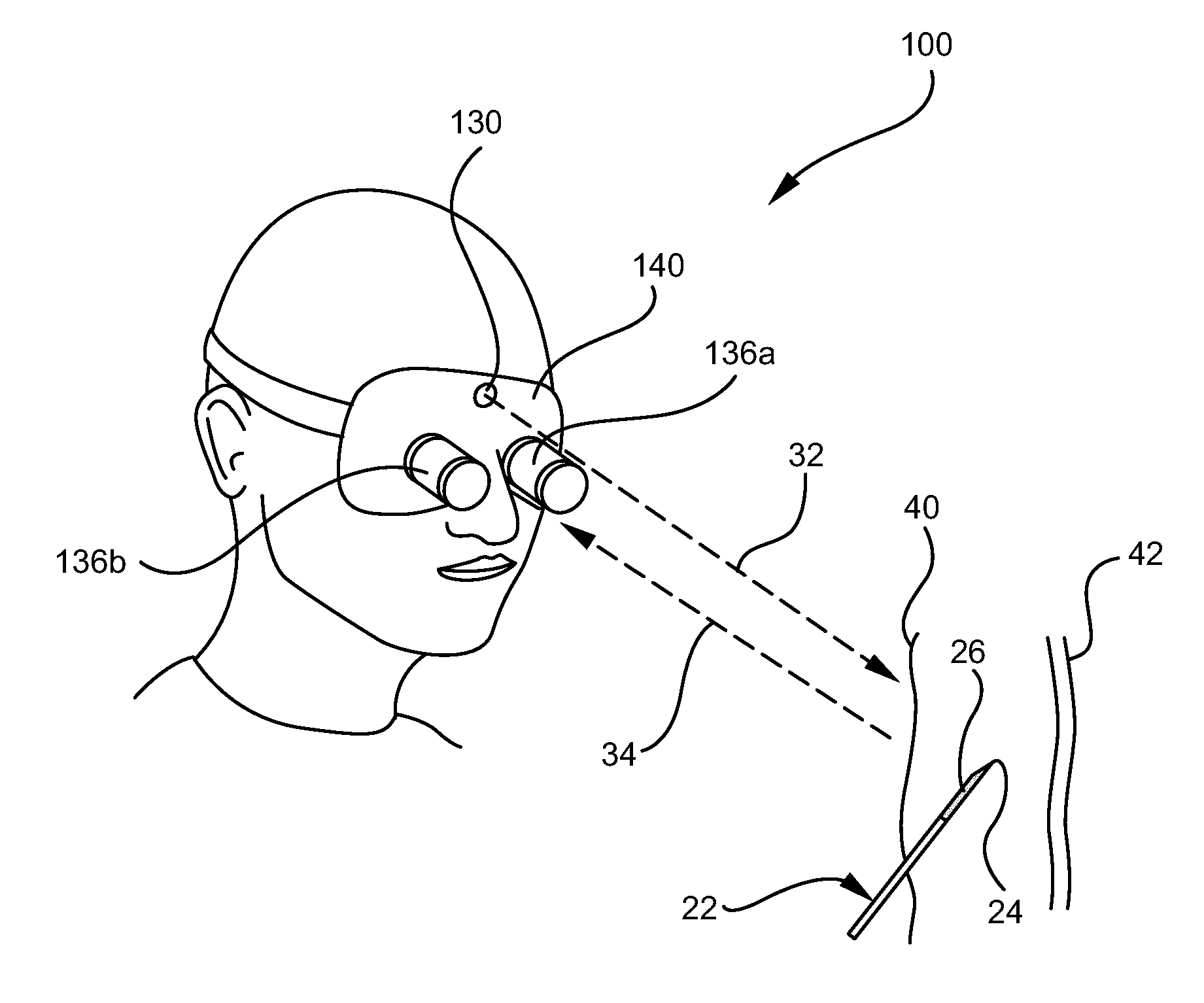
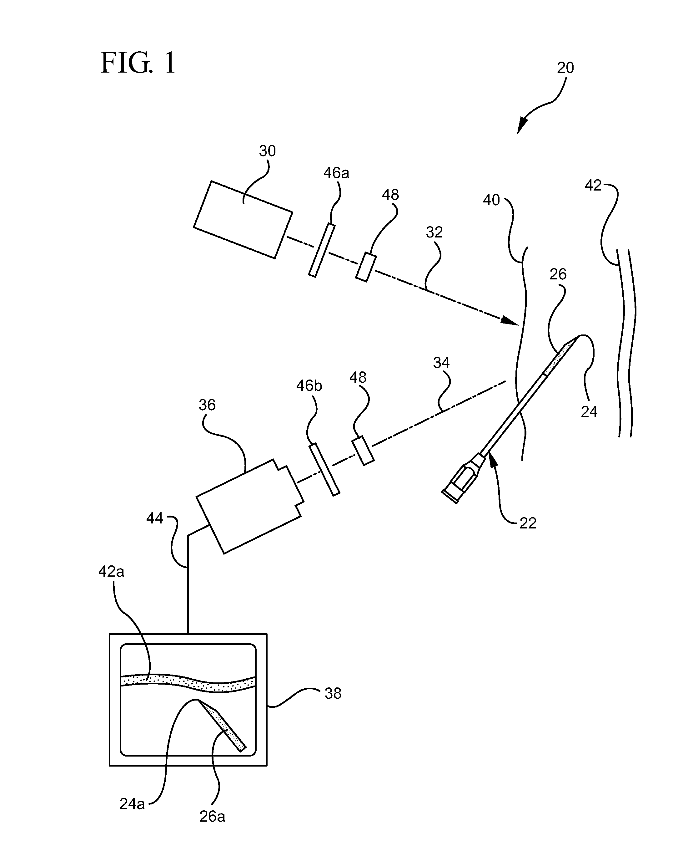
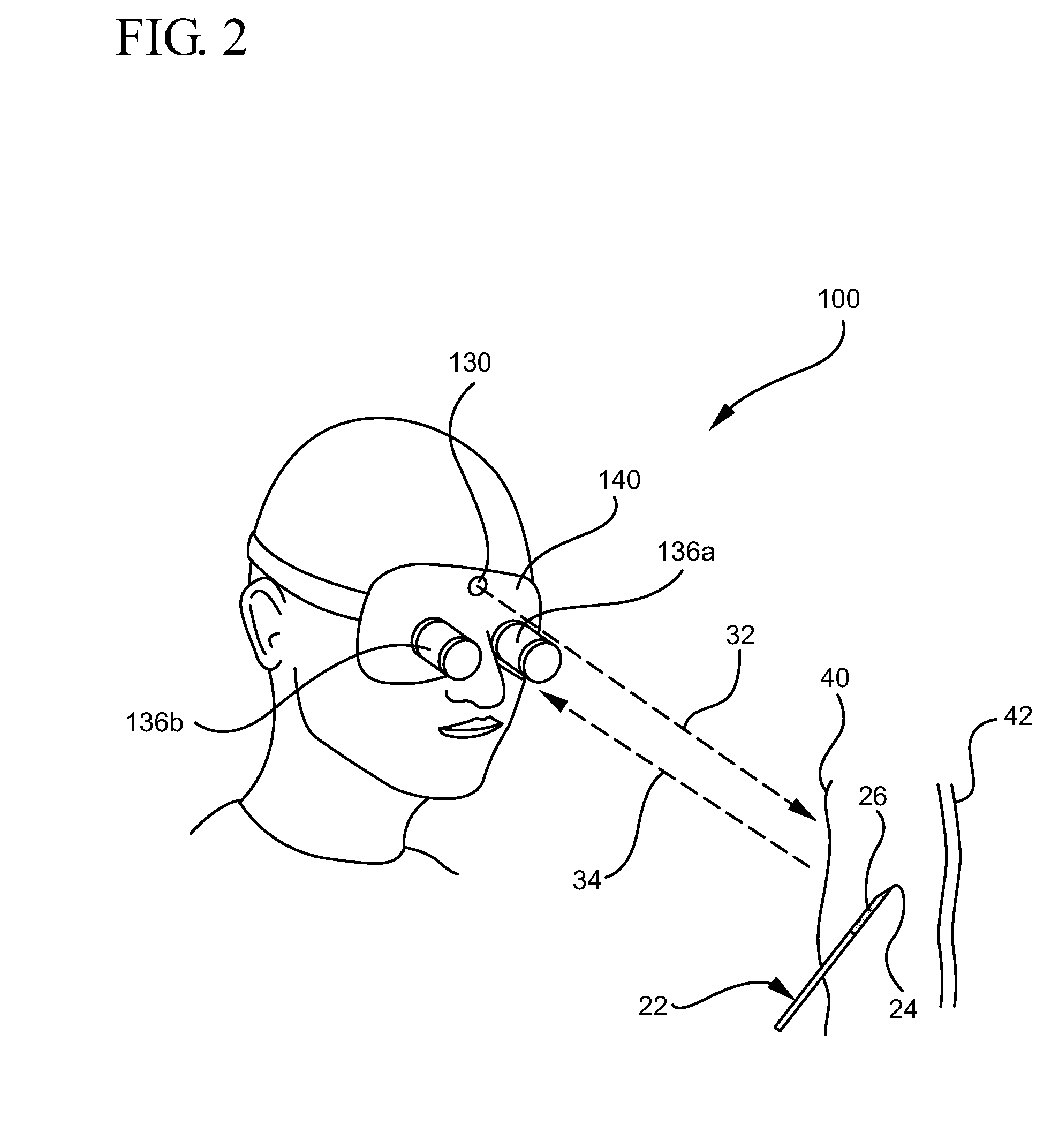
[0028]FIG. 1 illustrates an embodiment of a system for visualizing needle entry into a body. The system includes a radiation visualization device or system 20 (e.g. Digital VeinVue from VueTek Scientific) which includes a radiation light source 30, a radiation detector 36, and a display 38. In some embodiments the radiation is infrared (IR) radiation, in other embodiments th...


PUM


Abstract

A system for visualizing needle entry into a body is presented. The system includes a needle for entering a body. The needle is coated with a radiation scattering coating on at least a portion of the needle. The system additionally includes a radiation visualization device which detects reflected radiation directed at a target body and enables medical personnel to view anatomical structures such as a blood vessel along with the inserted needle within a body.

Description

RELATED APPLICATIONS[0001]This application claims the benefit of U.S. Provisional Application No. 61 / 224,133, filed Jul. 9, 2009, entitled NEEDLE COATING FOR ENHANCED VISUALIZATION. This application claims priority to and incorporates herein by reference the provisional application.BACKGROUND OF THE INVENTION[0002]The present invention relates to a system and method for visualizing a needle within biological tissue. More particularly, the invention relates to a system and method for visualizing a needle and locating anatomical structures within a body by utilizing equipment sensitive to the unique absorption and scattering characteristics of the target structures.[0003]Every day many hundreds-of-thousands of medical procedures involving the puncturing of blood vessels are performed. Venipuncture, as it is known, is required in order to administer emergency fluids, blood components, and anesthetics during operations, or to allow the drawing of blood for biochemical analysis. Venipunc...

Claims


Application Information

Patent Timeline
Patent Type & Authority Patents(United States)
IPC IPC(8): A61B5/05A61B5/00A61B6/00
CPCA61B5/0059A61B19/5225A61B5/1422A61B5/15003A61B5/150389A61B5/150511A61B5/150519A61B5/150748A61B5/1535A61B5/489A61B5/155A61B17/3403A61B19/5212A61B2019/262A61B2019/5441A61B5/150267A61B2090/502A61B90/361A61B90/37A61B2090/3941
Inventor ZEMEL, MARC I.
Owner BECTON DICKINSON & CO
Why Eureka
Try Eureka