Flanged member and a flange joint comprising flange members

Inactive Publication Date: 2012-11-20
VERAX ENG
View PDF10 Cites 5 Cited by
  • Summary
  • Abstract
  • Description
  • Claims
  • Application Information

AI Technical Summary

Benefits of technology

[0027]Thus, by the present invention, the advantage is obtained of a flanged member that in unloaded state is compensated for the deformation it is foreseen to be subject to when it is in a loaded state. Thus, also in the loaded state, you have a flanged joint that has sealing surfaces abutting against each other with metal to metal contact, all the way in to the fluid pressure, i.e. all the way in to the edge closest to the opening. Consequently, the joint is tight.

Problems solved by technology

If you fail ever so little with the flatness, the risk following therewith is also avoided of the end surface instead becoming somewhat convex, which is a large disadvantage as has been explained above.

Method used


Image

  • Flanged member and a flange joint comprising flange members
  • Flanged member and a flange joint comprising flange members
  • Flanged member and a flange joint comprising flange members

Examples


Embodiment Construction

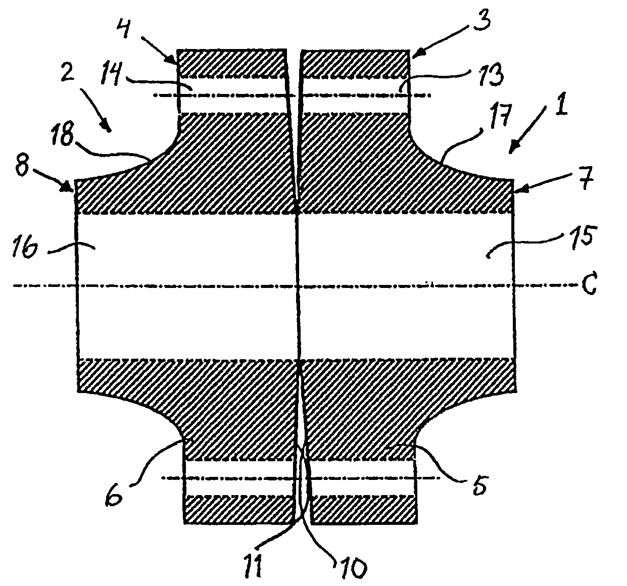
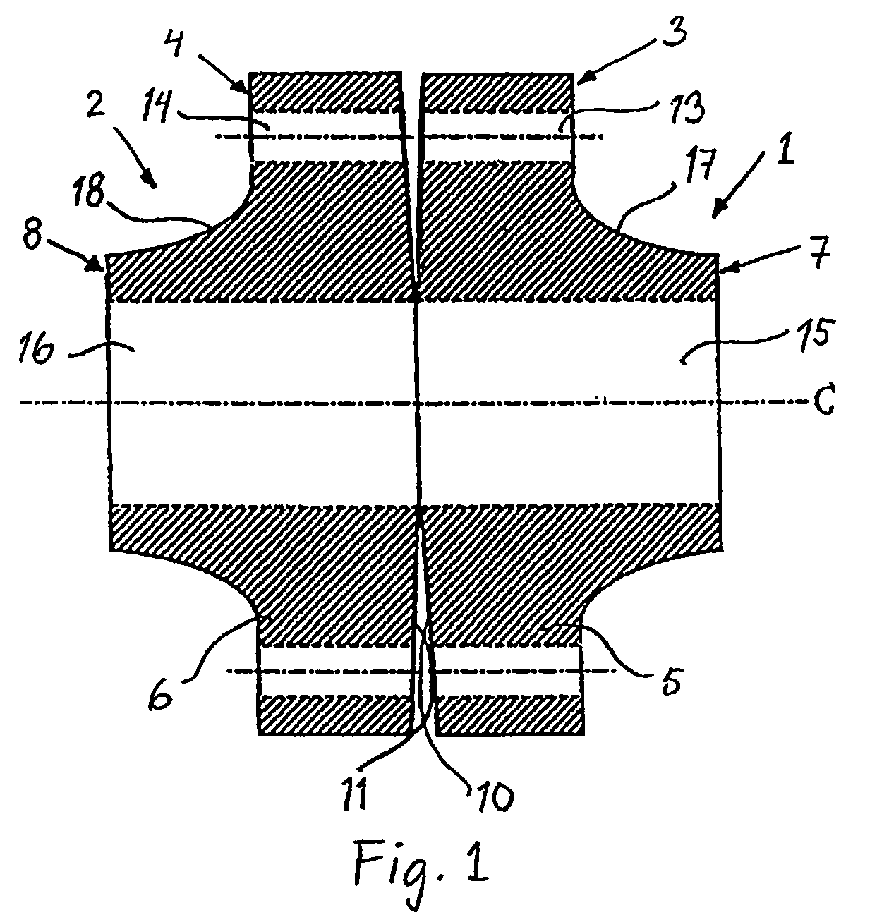
[0032]The joint shown in FIG. 1 comprises two flanged members 1, 2, each having a first end 3, 4 provided with a collar or flange 5, 6, as well as a second non-flanged end 7, 8. The flanged end 3, 4 of the respective flanged members has an end surface 10, 11 that in this case also is a contact surface, i.e. a surface intended to abut against a corresponding surface of the opposite flanged member, after assembly. The flanges 5, 6 extend preferably 360° and are provided with through borings 13, 14. At joining, the flanges are bolted together to a joint by means of bolts that are inserted through said borings. Usually, there are a number of borings arranged evenly distributed around the flange. All through the flanged members, a tubular duct 15, 16 extends. Here, the transition area 17, 18 between the flange and the non-flanged end consists of an elliptically shaped area. The illustrated joint is a non-gasketed and seal-free joint.

[0033]The end surfaces 10, 11 of the flanged members fa...


PUM


Abstract

A flanged member (1), intended to be included as a component in a flanged joint, for installation in a pressure equipment device, and having a first flanged end (3) having a first end surface (10) intended to be assembled together with another end surface (4) of a flanged end (11) on another, second flanged member (2) constituting a second component in the flanged joint. The first end surface is slightly concave in the radial direction over at least a part of the extension thereof in the radial direction.

Description

BACKGROUND OF THE INVENTION[0001]The present invention relates to a flanged member intended to be included as a component in a pressure equipment device, as well as a joint comprising two joint halves in the form of two flanged members and included in a pressure equipment device.[0002]It has been known for a long time to join different parts and components in pressure equipment devices, preferably pipe systems, by using flanged members. By flanged member, also called flange member or only flange, is here intended not just a pipe member, one end of which has been provided with a ring-shaped collar or flange, but also different components which may be included in a pipe system and that have at least one flanged end. It may, for instance, pertain to valves, Y-pieces or joint parts which may have one or more flanged ends for connection to other parts in the pipe system, vessels having a flange for the mounting of a lid, halves of casings for axial flow turbines or the like. The expressi...

Claims


Application Information

Patent Timeline
Patent Type & Authority Patents(United States)
IPC IPC(8): F16B1/00F16D1/033F16D3/00F16L23/032
CPCF16L23/032Y10T403/366Y10T403/645F16B2200/506
Inventor WEBJORN, JAN
Owner VERAX ENG
Why Eureka
Try Eureka