Immersion projection micro steriolithography

Pending Publication Date: 2021-08-05
BMF NANO MATERIAL TECH CO LTD
View PDF2 Cites 1 Cited by
  • Summary
  • Abstract
  • Description
  • Claims
  • Application Information

AI Technical Summary

Benefits of technology

[0009]The present invention provides methods to more precise control, with greater speed, the layer thickness in a bigger printing area, for example, 10 cm×10 cm printing area with 10 um layer thickness. In one embodiment, the present method submerges the printing head in the photo-sensitive resin by few millimeters, in another embodiment the printing head is few hundred microns above

Problems solved by technology

When these two coordinate systems are not parallel due to the assembly tole

Method used


Image

  • Immersion projection micro steriolithography
  • Immersion projection micro steriolithography
  • Immersion projection micro steriolithography

Examples


Embodiment Construction

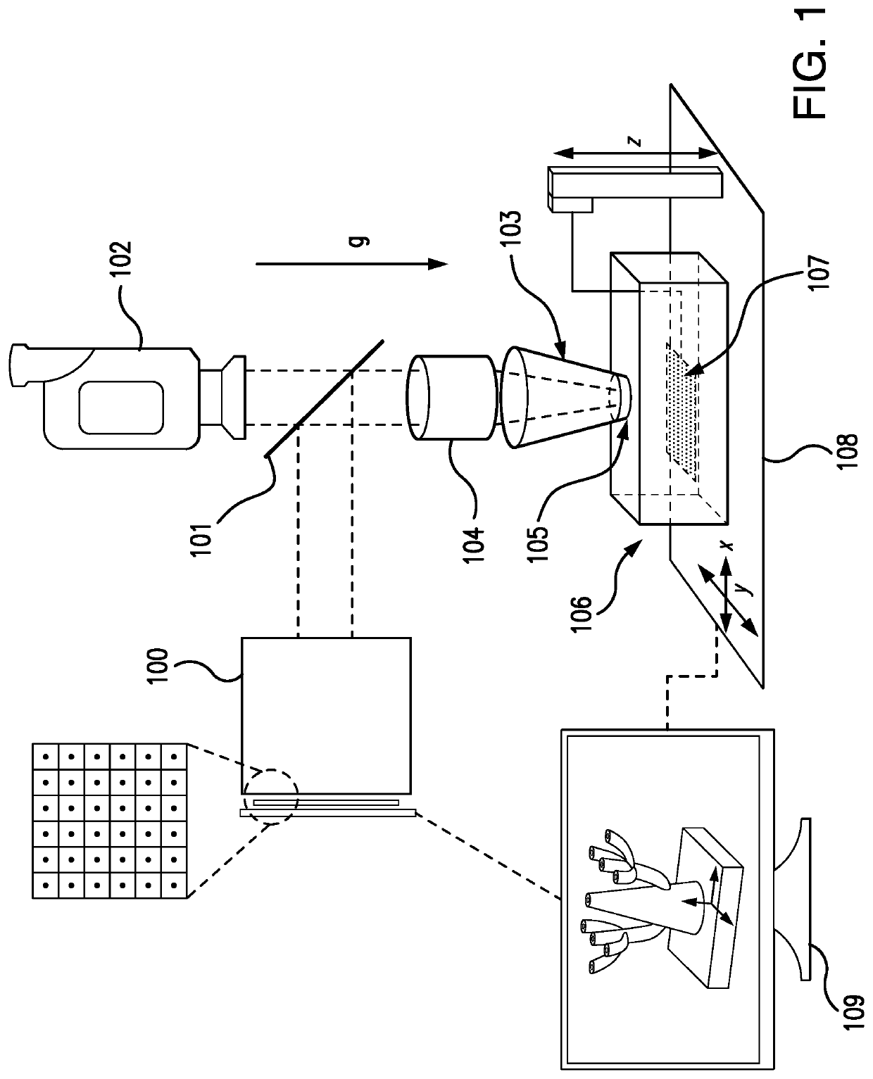
[0032]The invention provides a method for high resolution, projection micro stereolithography for 3-D printing of a sample, object item etc., wherein one or more coating layers, typically multiple coating layers, are printed over a larger area and at faster speeds than presently available, the method comprises:

[0033]generating a 3D digital model of the sample or object to be printed in a computer, and then slicing the digital model into a sequence of images wherein each of the images of the sequence represents a layer of the 3D digital model, so that after each layer is applied the sample or object has been formed.

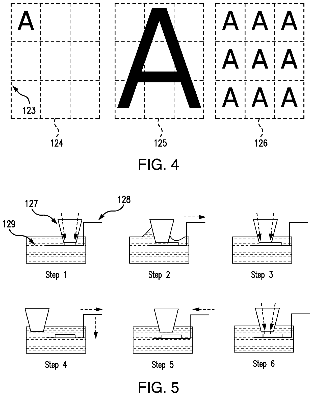
[0034]In the present method, a transparent printing head comprising a flat tip at one surface is positioned relative to a resin vat containing a photo-sensitive resin and a substrate for holding the sample during printing, e.g., a sample holder, wherein the flat tip is in contact with the photo-sensitive resin, the transparent printing head is moved into position for selec...


PUM

PropertyMeasurementUnit
Lengthaaaaaaaaaa
Lengthaaaaaaaaaa
Lengthaaaaaaaaaa

Abstract

A method for high resolution projection micro stereolithography for 3-D printing comprising: generating a 3D digital model of the sample to be printed in a computer, slicing the digital model into a sequence of images, wherein each of the images of the sequence represents a layer of the 3D digital model, positioning a transparent printing head relative to a resin vat containing a photo-sensitive resin, moving the transparent printing head into position for selectively exposing the photosensitive resin, sending an image from the sequence of images to a LCD or DLP chip, and together with a light source projecting the image through a lens onto the flat tip of the transparent printing head to initiate cure of the photosensitive resin in areas where the projected image allows light from the light source to reach the photosensitive resin.

Description

[0001]The present invention provides improved methods for faster and larger-area printing without sacrificing the resolution available in existing projection micro stereolithography methods, for example, a 3D printing technology making use of an oxygen permeable membrane immersed in the photo-sensitive resin, in particular, a membrane moving in the resin stepwise during the large-area printing. The methods invented here are not limited to this 3D printing method, it is also valid for any other type of method using laser beam / spot scanning in 3D printing.BACKGROUND[0002]Stereolithography was originally conceived as a rapid prototyping technology. Rapid prototyping refers to a family of technologies that are used to create true-scale models of production components directly from computer aided design (CAD) in a rapid manner, i.e., faster than before. Since its disclosure in U.S. Pat. No. 4,575,330, stereolithography has greatly aided engineers in visualizing complex three-dimensional ...

Claims


Application Information

Patent Timeline
IPC IPC(8): B29C64/124B29C64/209B29C64/245B29C64/232B29C64/236B29C64/286B29C64/393B29C64/364
CPCB29C64/124B29C64/209B29C64/245B29C64/232B33Y10/00B29C64/286B29C64/393B29C64/364B29C64/236B29C64/129B29C64/227B29C64/277B33Y30/00B33Y50/02
Inventor XIA, CHUNGUANGSLOCUM, ALEXANDERKAWOLA, JOHNBASSI, JASON
Owner BMF NANO MATERIAL TECH CO LTD
Why Eureka
Try Eureka