
Static reactive power compensation device based on energy method and control method thereof

A technology of static reactive power compensation and control method, which is applied in the field of power transmission and distribution, and can solve problems such as poor convergence, dependence, and large amount of calculation

Inactive Publication Date: 2010-11-17
NORTHEASTERN UNIV
View PDF2 Cites 19 Cited by
  • Summary
  • Abstract
  • Description
  • Claims
  • Application Information

AI Technical Summary

Problems solved by technology

Conventional reactive power optimization methods have the following problems to varying degrees, such as relying on accurate mathematical models; strict requirements on the initial point; reactive power optimization methods based on derivative information have certain restrictions on the objective function and constraints; The "curse of dimensionality" problem caused by the increase in the number of variables is difficult to solve
Moreover, there are problems such as large amount of calculation, high memory requirements, poor convergence, poor stability, and certain difficulties in dealing with inequalities to varying degrees, and its application is limited to a certain extent.
Aiming at the shortcomings of conventional optimization methods to solve reactive power optimization problems, many researchers have applied artificial intelligence methods to the field of reactive power optimization research, but so far there is no mature reactive power optimization algorithm based on nonlinear programming
[0003] Based on the above analysis, it can be seen that this field is still in the research stage in China at present, and there is no recognized and effective product for static var compensation devices. Conventional optimization methods have relatively large limitations in dealing with such problems, and intelligent optimization methods are different from them. Compared with , it has huge advantages and potentials, and the demand for this function by power companies is also very urgent

Method used


Image

  • Static reactive power compensation device based on energy method and control method thereof
  • Static reactive power compensation device based on energy method and control method thereof
  • Static reactive power compensation device based on energy method and control method thereof

Examples


Embodiment Construction

[0133] The present invention will be described in further detail below in conjunction with the accompanying drawings and embodiments.

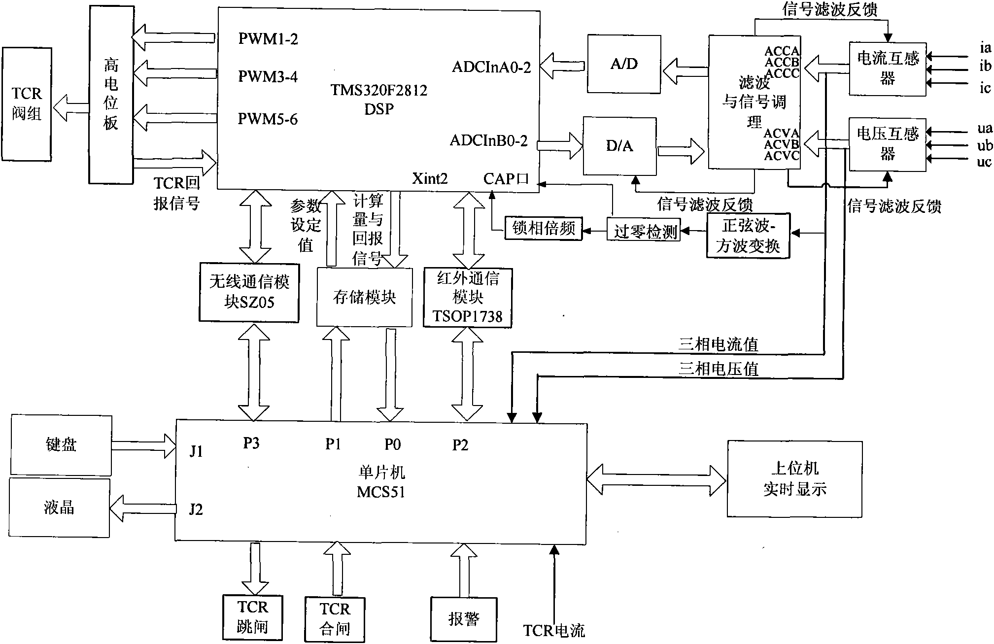
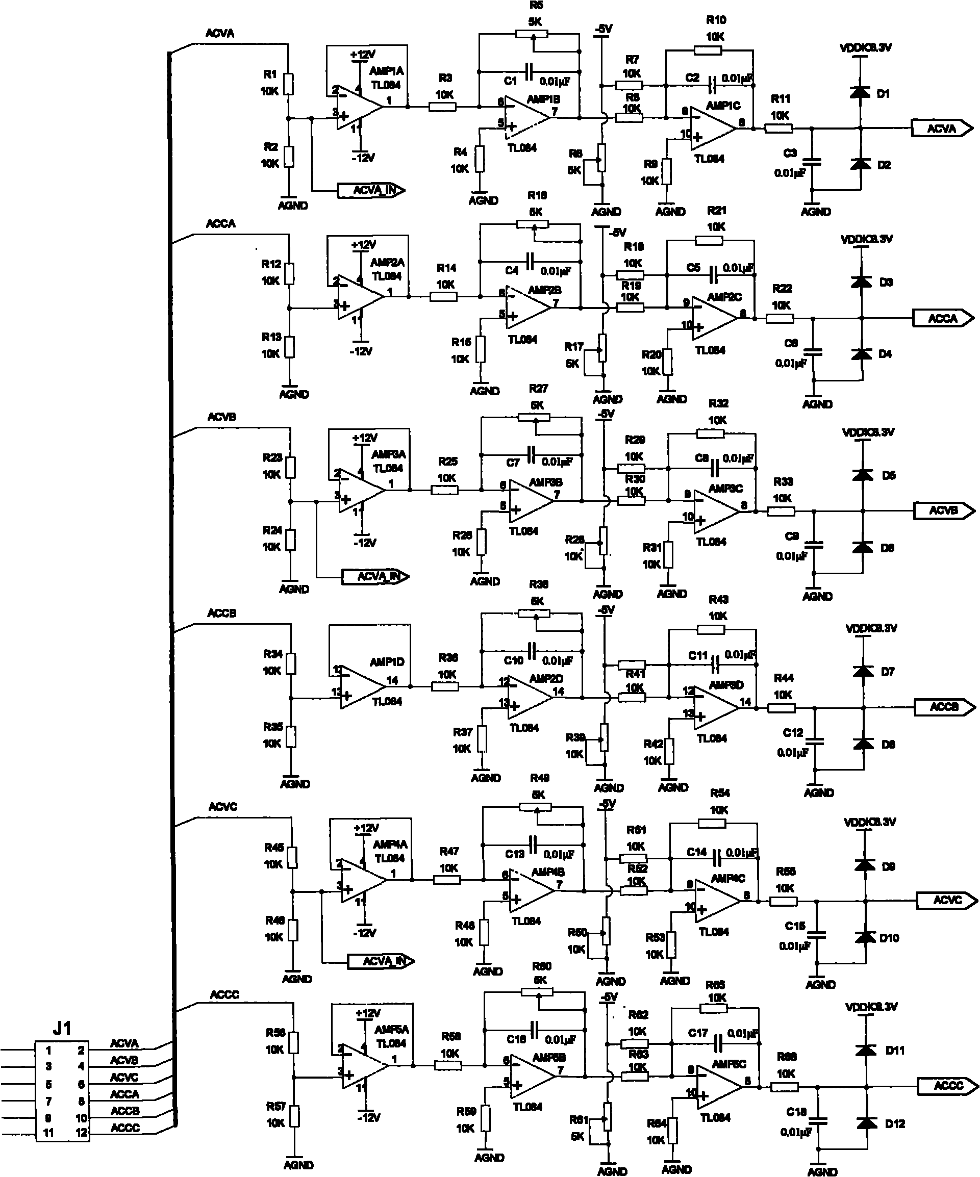
[0134] Figure 1 to Figure 10 It is the schematic diagram of the circuit of the present invention, the transformer group, the filter and signal conditioning module, the A / D conversion module, the calculation module, the storage module, the phase-locked loop circuit module, the communication module, the display and keyboard operation module, the first of the transformer group The output terminal is connected to the first input terminal of the filtering and signal conditioning module, the second output terminal of the transformer group is connected to the second input terminal of the filtering and signal conditioning module, and the third output terminal of the transformer group is connected to the input of the phase-locked loop circuit module terminal, the output terminal of the phase-locked loop circuit module is connected to the capture termi...


PUM


Abstract

The invention relates to a static reactive power compensation device based on an energy method and a control method thereof, belonging to the technical field of power transmission and distribution. The invention comprises a mutual inductor group, a filtering and signal conditioning module, an A / D conversion module, a computing module, a memory module, a phase-locked loop circuit module, a communication module and a display and keyboard operation module. The invention can evaluate and analyze possibly potential dangers of a power grid by adopting energy function method, predict the influence on the stable operation of the power grid possibly resulted from faults by establishing an anticipated accident list, carry out scientific, effective and real-time analysis and evaluation on the power grid state and carrying out integral cognition on the power grid performance as complete as possible, thereby quantitatively evaluating the operation state level of the power grid; and the invention effectively avoids an algorithm from falling to local optimum by adopting an improved particle intelligent swarm algorithm based on a fuzzy control theory.

Description

technical field [0001] The invention belongs to the technical field of power transmission and distribution, and in particular relates to a static reactive power compensation device and a control method based on an energy method. Background technique [0002] With the occurrence of many power grid equipment accidents at home and abroad in recent years, people have a new understanding of the importance of power grid stability. How to monitor and compensate reactive power reasonably, timely and effectively has become a power-related issue today. An important issue that the industry needs to solve urgently. With the development of my country's electric power industry, the scale of the power grid is constantly expanding, especially the structure of the distribution network is becoming more and more complex, and the requirements for the reliability and quality of power supply are getting higher and higher. SVC (Static Var Compensator) static dynamic reactive power compensation de...

Claims


Application Information

Patent Timeline
IPC IPC(8): H02J3/18G05B13/04
CPCY02E40/30
Inventor 张化光孙秋野杨珺杨东升佟忠正刘兆冰刘振伟董艳博孙旸子
Owner NORTHEASTERN UNIV
Learn More