Clutch arrangement and two-speed gearbox

a two-speed gearbox and clutch technology, applied in the direction of mechanical actuated clutches, interengaging clutches, gearing, etc., can solve the problems of unfavorable controllability and operating reliability, and achieve the effect of high rigidity of the actuator system and short shift time in the clutch

Inactive Publication Date: 2013-11-21
GETRAG GETRIEBE & ZAHNRADFABRIK HERMANN HAGENMEYER GMBH & CO KG
View PDF3 Cites 4 Cited by
  • Summary
  • Abstract
  • Description
  • Claims
  • Application Information

AI Technical Summary

Benefits of technology

[0044]Overall, the present invention affords a short shift time in a clutch arranged on a shaft and / or a high rigidity of the actuator system. Furthermore, depending on the embodiment, the invention makes it possible to achieve at least one of the following advantages.
[0045]Firstly, in the first aspect, through suitable support (for example an O arrangement) in the gearbox housing, the shaft itself can act as tension bolt between two housing halves of the housing. Furthermore, it is possible to compensate for a deformation of the gearbox housing when an actuating force is exerted.

Problems solved by technology

Although the housing is usually of relatively rigid construction, the ensuing actuating times of such power-shift clutches are in practice often long, which may be disadvantageous in terms of controllability and operating reliability.

Method used


Image

  • Clutch arrangement and two-speed gearbox
  • Clutch arrangement and two-speed gearbox
  • Clutch arrangement and two-speed gearbox

Examples


Embodiment Construction

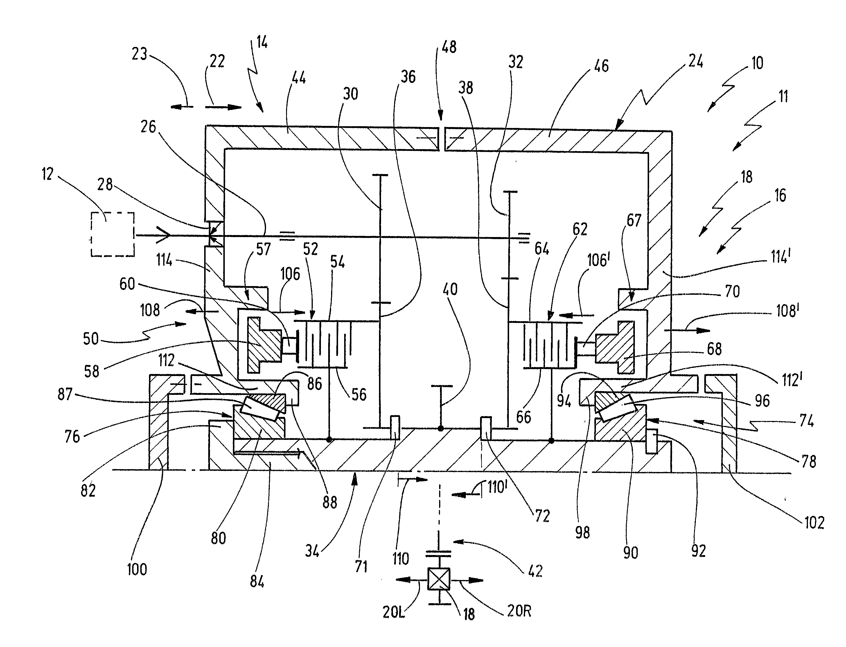
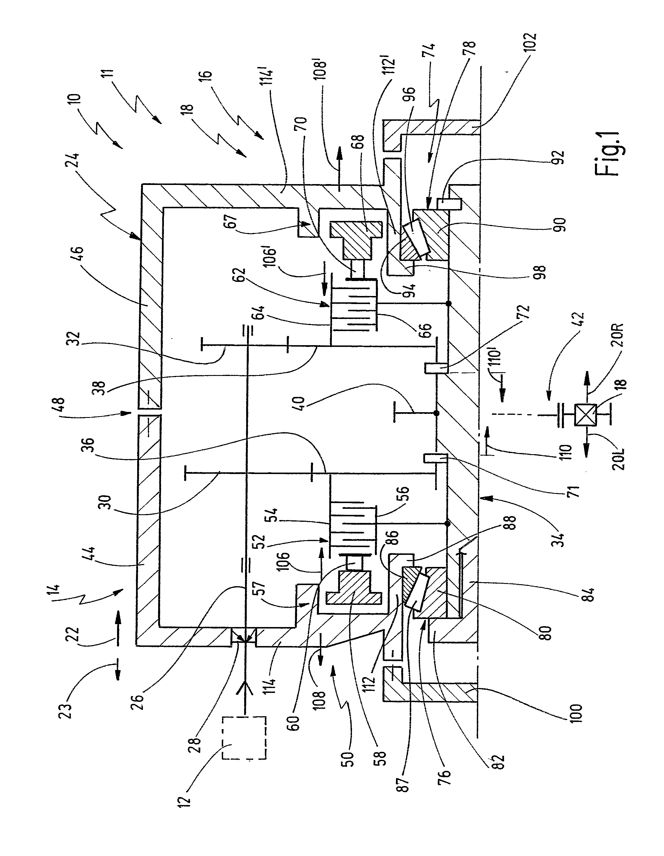
[0057]FIG. 1 in schematic form represents a drivetrain for a motor vehicle, which is generally denoted 10. The drivetrain 10 serves for driving a motor vehicle 11, not represented further, and comprises a prime mover 12. The prime mover 12 may be an electric motor, for example, so that the vehicle is embodied as a purely electrical vehicle. The prime mover may also be a hybrid drive unit, however, for example in the form of a range-extender drive, or also a conventional internal combustion engine.

[0058]The propulsive power of the prime mover 12 is fed into a transmission arrangement 14, which comprises a two-speed gearbox 16. An output of the two-speed gearbox 16 is connected to a differential 18, which distributes propulsive power to two driven wheels 20L and 20R. In FIG. 1 a first longitudinal direction is denoted by 22. The opposite, second longitudinal direction is denoted in FIG. 1 by 23.

[0059]The two-speed gearbox 16 comprises a housing 24, which may be made from metal, for ex...


PUM


Abstract

Clutch arrangement for a motor vehicle gearbox. The clutch arrangement has a housing and a clutch. The clutch is arranged in the housing and is arranged concentrically with a shaft, which extends in a longitudinal axis. The shaft is supported on the housing by means of a first shaft bearing adjacent to the clutch and by means of a second shaft bearing spaced at an axial distance from the clutch. The clutch arrangement has an actuator arrangement for actuating the clutch. The actuator arrangement is designed to exert an actuating force on the clutch in a first longitudinal direction. The actuator arrangement here being axially braced on the housing and a force flux being introduced into the shaft as a result of the actuating force. The first shaft bearing is arranged so that the force flux introduced into the shaft can be axially braced on the housing by way of the first shaft bearing.

Description

CROSS-REFERENCE TO RELATED APPLICATIONS[0001]This application claims the priority of German patent application DE 10 2012 010 170, filed May 19, 2012.BACKGROUND OF THE INVENTION[0002]The present invention relates to a clutch arrangement, particularly for a motor vehicle gearbox, having a housing, having a clutch which is arranged in the housing and which is arranged concentrically with a shaft, which extends in a longitudinal axis, the shaft being supported on the housing by means of a first shaft bearing adjacent to the clutch and by means of a second shaft bearing spaced at an axial distance from the clutch, and having an actuator arrangement for actuating the clutch, the actuator arrangement being designed to exert an actuating force on the clutch in a first longitudinal direction, the actuator arrangement here being axially braced on the housing and a force flux being introduced into the shaft as a result of the actuating force.[0003]Clutch arrangements of this type are known in...

Claims


Application Information

Patent Timeline
Patent Type & Authority Applications(United States)
IPC IPC(8): F16D13/52F16D13/58
CPCF16D13/52F16D13/58F16D21/04F16D25/082F16D25/10F16H3/089F16H57/021F16H2200/0034Y10T74/19614Y10T74/19288
Inventor RUEHLE, GUENTERBAUSCH, JOCHENSODEMANN, HARALDANSPANN, STEFAN
Owner GETRAG GETRIEBE & ZAHNRADFABRIK HERMANN HAGENMEYER GMBH & CO KG
Why Eureka
Try Eureka