Method and apparatus of stored energy management in battery powered vehicles

a technology of stored energy and battery power, applied in the direction of electrical generators, transportation and packaging, sustainable buildings, etc., can solve the problems of reducing the lifetime of the battery, and affecting the service life of the battery

Active Publication Date: 2012-11-20
ALCATEL LUCENT SAS
View PDF8 Cites 27 Cited by
  • Summary
  • Abstract
  • Description
  • Claims
  • Application Information

AI Technical Summary

Benefits of technology

[0009]Our solution is to provide a secondary battery and charging system within an electric car or other electric drive vehicle. The secondary battery may, e.g., be owned by the electric utility. The battery is removable and can be charged and discharged independently of the primary car battery system. The utility can use the secondary battery to implement V2G functionality without the constraints on usage described previously. If, e.g., the secondary battery is not owned by the user, there is less cause for the user to resist participation in V2G.
[0010]Accordingly, in an embodiment, a power assembly includes a primary battery unit and a secondary battery unit that has no more than 20% the total discharge capacity of the primary battery unit and is removable from the primary unit. The power assembly further includes switching circuitry configured to selectively draw electric power from one or the other of the primary and secondary battery units, and switching circuitry configured to independently charge the primary and secondary battery units. By “independently” is meant that each battery unit can be charged without substantially affecting the charging rate of the other, and that at least one can be charged without charging the other.

Problems solved by technology

One drawback of V2G as currently envisaged is that it may have limited acceptability to consumers.
This poses a problem not only because the consumer will view the utility company's use as denying him the full benefit of his property (i.e., the battery), but also because every car battery has a limited number of charge / discharge cycles, and the utility company's use will therefore reduce the lifetime of the battery.
Although this may overcome some resistance by consumers, the basic conflict between maintaining a full charge and permitting charge flexibility is left unresolved.

Method used


Image

  • Method and apparatus of stored energy management in battery powered vehicles
  • Method and apparatus of stored energy management in battery powered vehicles
  • Method and apparatus of stored energy management in battery powered vehicles

Examples


Embodiment Construction

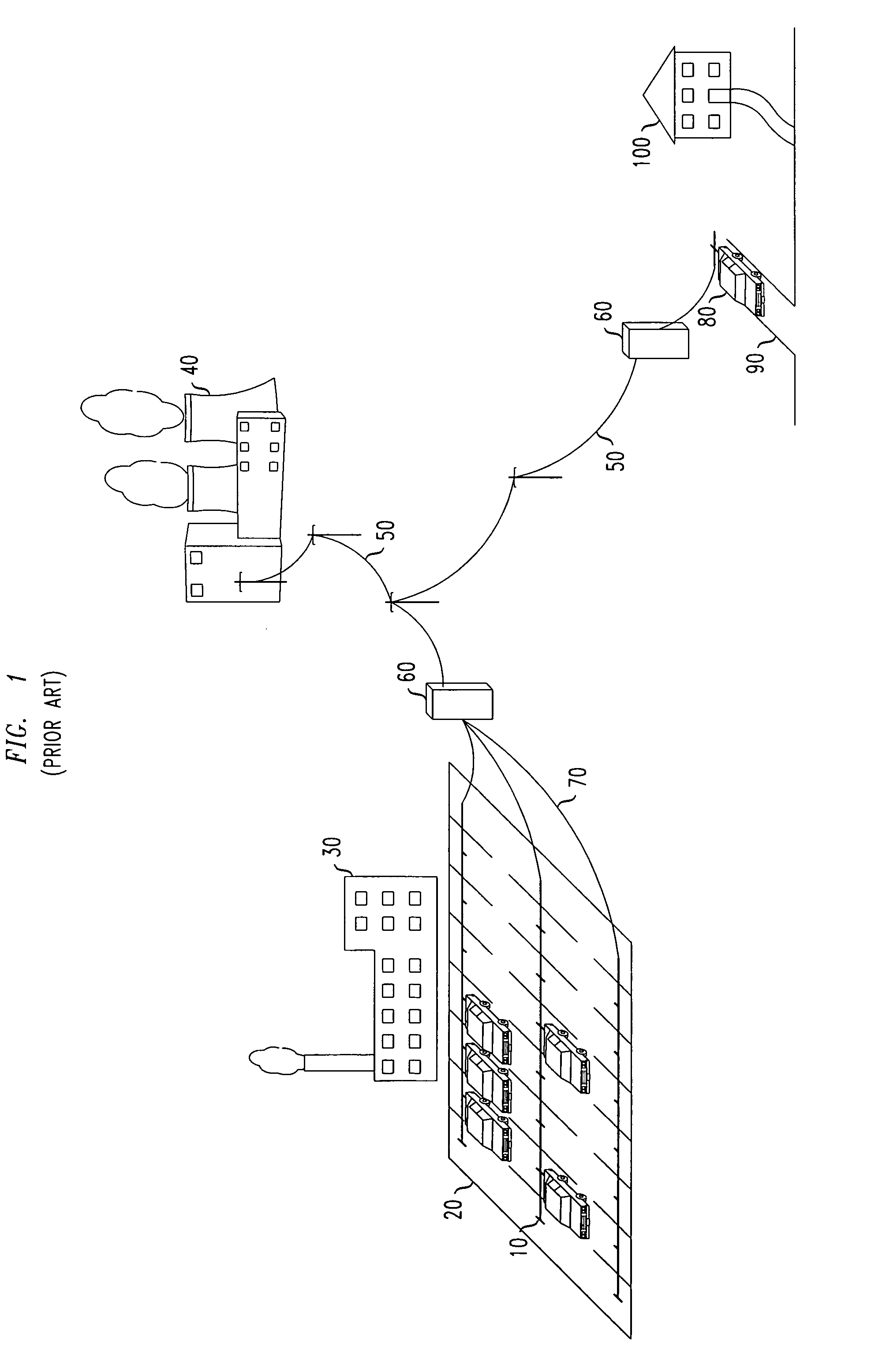
[0021]FIG. 1 shows a typical scenario in which electric cars may be placed in contact with an electric utility for purposes of load balancing. Employee cars 10 are parked in parking lot 20 of workplace buildings 30. An electric power plant 40 is advantageously situated relatively nearby to minimize transport loss.

[0022]Power line 50 delivers electric power from the power plant to utility box 60, from which it is distributed to each of the parking spaces of lot 20 by conductive distribution lines 70. At each parking space, the electrical storage assembly of the respective car plugs into a receptacle (not shown) in electrical contact with one of the lines 70. The receptacle provides electrical continuity for charging and discharging the car's batteries.

[0023]It is also advantageous to provide a communication medium between the car and the electric utility, for example so that the utility can read the state of charge of the car batteries. Various alternative communication media are kno...


PUM


Abstract

A secondary battery and charging system are provided within an electric car or other electric drive vehicle. The secondary battery may, e.g., be owned by the electric utility. The battery is removable and can be charged and discharged independently of the primary car battery system. The utility can use the secondary battery to implement vehicle-to-grid functionality.

Description

CROSS REFERENCE TO RELATED APPLICATION[0001]This application is a continuation-in-part of U.S. patent application Ser. No. 12 / 587.598 filed Oct. 9, 2009 now abandoned by C. White and W. Lee under the title, “Method and Apparatus of Stored Energy Management in Battery Powered Vehicles”.FIELD OF THE INVENTION[0002]The invention relates to the storage and utilization of electricity in vehicles that derive at least some power from batteries.ART BACKGROUND[0003]It has long been known that distributed schemes for production, storage, and retrieval of electric energy can make electric power distribution by public utilities more cost effective. For example, small or medium-scale facilities storing energy in the form of charged batteries, pumped water, compressed gas, or the like can be connected to the electric power grid and used to add power to the grid during outages and periods of high demand. Conversely, the distributed storage facilities can draw energy from the grid during periods of...

Claims


Application Information

Patent Timeline
Patent Type & Authority Patents(United States)
IPC IPC(8): H02J7/00H02J7/14
CPCB60L11/1816B60L11/184B60L11/1846H01M10/441H02J3/32H02J7/0004H02J7/0013B60L11/1842B60L11/1848B60L11/1822Y02T10/7088B60L2230/16H02J13/002H02J13/0062H02J13/0075H02J2007/0001Y02E60/721Y02T10/7005Y02T10/7055Y02T90/121Y02T90/124Y02T90/128Y02T90/14Y02T90/163Y02T90/168Y02T90/169Y04S10/126Y04S30/12Y04S30/14B60L53/14B60L53/80B60L53/64B60L55/00B60L53/65B60L53/665B60L53/305H02J7/00045H02J7/00036H02J13/00007H02J2310/48H02J13/00016H02J13/00024H02J7/00047Y02E60/00Y02T10/70Y02T10/7072Y02T90/12Y02T90/167Y02T90/16Y04S40/124Y02E60/10Y02B90/20H02J3/322H02J7/04
Inventor WHITE, CHRISTOPHER A.LEE, WONSUCK
Owner ALCATEL LUCENT SAS
Why Eureka
Try Eureka