Overcurrent protective wire wound resistor

a resistor and overcurrent technology, applied in the field of resistors, can solve the problems of increasing the cost and size of electronic products, and achieve the effect of lowering the cost and size of an electronic product connected

Active Publication Date: 2012-11-20
TY OHM ELECTRONICS WORKS
View PDF5 Cites 12 Cited by
  • Summary
  • Abstract
  • Description
  • Claims
  • Application Information

AI Technical Summary

Benefits of technology

[0008]An objective of the present invention is to provide an overcurrent protective wire

Problems solved by technology

However, the conventional wire wound resistor only targets at serving as a circuit component having a resistance value and connected to the external circuit components in a

Method used


Image

  • Overcurrent protective wire wound resistor
  • Overcurrent protective wire wound resistor
  • Overcurrent protective wire wound resistor

Examples


Embodiment Construction

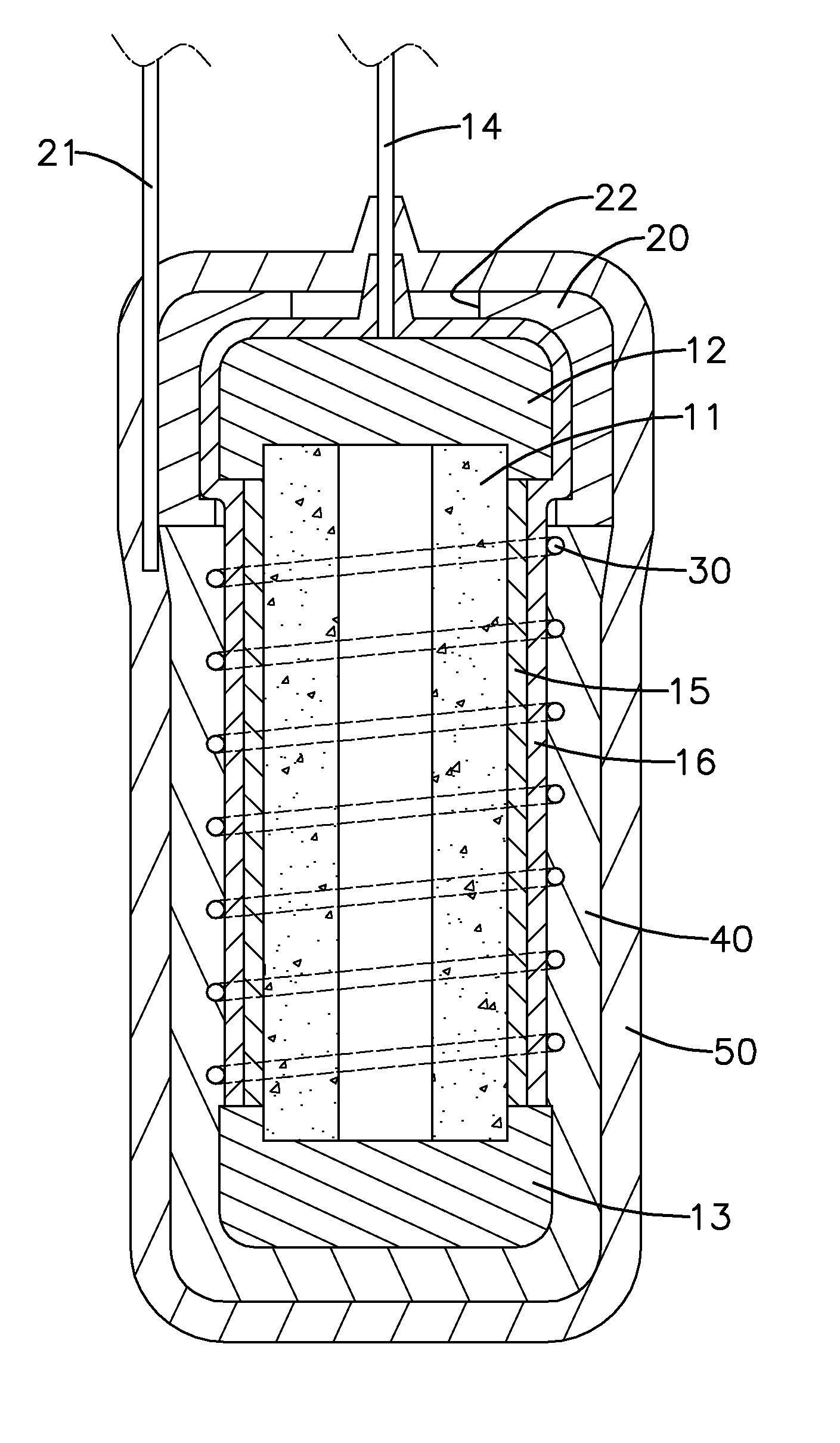
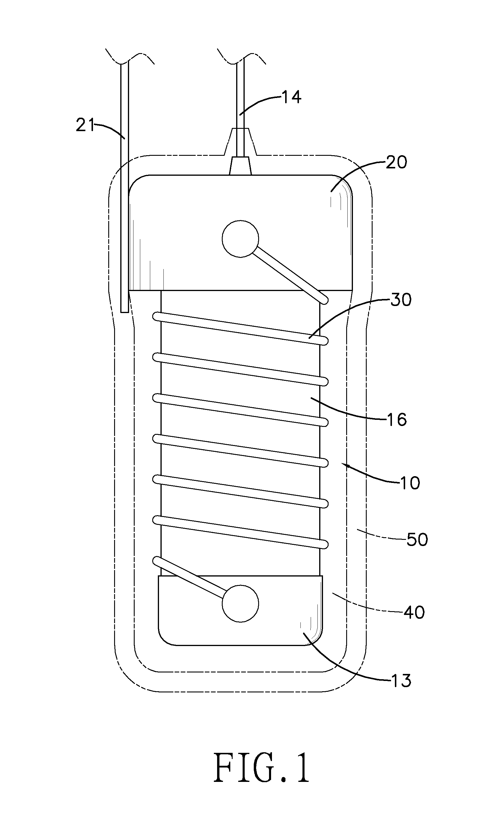
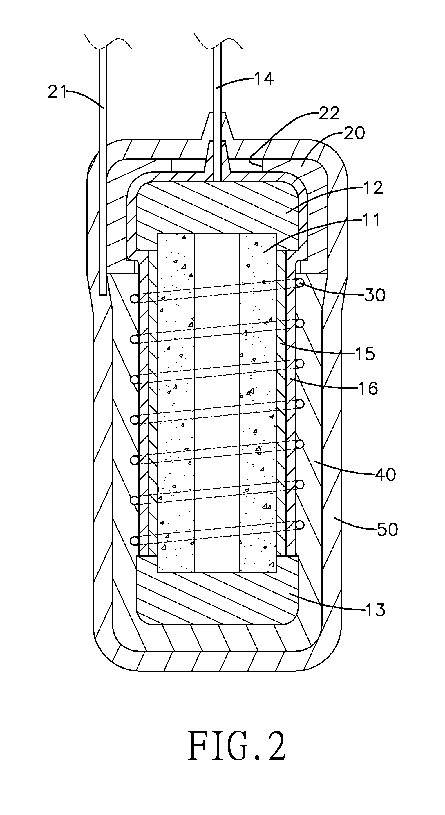
[0020]With reference to FIGS. 1 and 2, an overcurrent protective wire wound resistor in accordance with the present invention has a high-temperature opening core 10, a second contact cap 20 and a resistance wire 30.

[0021]The high-temperature opening core 10 has a rod 11, a first contact cap 12, a resistor connection seat 13, a low melting point conductive layer 15 and a high-temperature contractive insulation layer 16. The rod 11 has two opposite ends. The first contact cap 12 has a first lead wire 14 mounted thereon and two opposite ends. The first contact cap 12 and the resistor connection seat 13 are respectively mounted on the two opposite ends of the rod 11. The first lead wire 14 and the rod 11 are respectively mounted on the two opposite ends of the first contact cap 12. The low melting point conductive layer 15 is mounted around a periphery of the rod 11 and extends longitudinally to the first contact cap 12 and the resistor connection seat 13. The high-temperature contracti...


PUM


Abstract

An overcurrent protective wire wound resistor has a core, a second contact cap and a resistance wire. A first contact cap and a resistor connection seat are respectively mounted on two ends of a rod of the core. A low melting-point conductive layer is mounted around the rod and connected with the first contact cap and the resistor connection seat. A high-temperature contractive insulation layer is mounted around the low melting-point conductive layer and the first contact cap. The second contact cap is mounted around the contractive insulation layer. The resistance wire is connected to the resistor connection seat and the second contact cap. When current through the resistance wire abnormally increases, high temperature of the resistance wire melts the low melting point conductive layer to shrink the contractive insulation layer and open the low melting-point conductive layer and the resistor, thereby protecting the circuit connected to the resistor.

Description

BACKGROUND OF THE INVENTION[0001]1. Field of the Invention[0002]The present invention relates to a resistor and more particularly to an overcurrent protective wire wound resistor.[0003]2. Description of the Related Art[0004]Resistors are one of the indispensable components for manufacturing all kinds of electronic products and can be generally classified as fixed resistors and variable resistors. Among the fixed resistors, resistors having resistance wires wound around are called wire wound resistors.[0005]With reference to FIG. 5, a conventional wire wound resistor has a core 70 and a resistance wire 80. The core 70 has a rod 71 and two contact caps 72. The rod 71 has two opposite ends. The two contact caps 72 are respectively mounted on the two opposite ends of the rod 71. The resistance wire 80 is wound around a periphery of the rod 71 of the core 70. Two ends of the resistance wire 80 are electrically connected to the respective contact caps 72.[0006]The wire wound resistor is m...

Claims


Application Information

Patent Timeline
IPC IPC(8): H01C1/14
CPCH01C1/14H01C3/20H01C7/13
Inventor KUO, SAMUEL
Owner TY OHM ELECTRONICS WORKS
Why Eureka
Try Eureka