Compound leverage hand tool with interchangeable tool head

a technology of hand tools and tool heads, which is applied in the field of hand tools, can solve the problems of increasing the total cost, wasting resources, and affecting the use of the tool head, and avoiding the use of the handle portion of the tool,

Inactive Publication Date: 2012-11-27
MIDWEST TOOL & CUTLERY
View PDF27 Cites 15 Cited by
  • Summary
  • Abstract
  • Description
  • Claims
  • Application Information

AI Technical Summary

Benefits of technology

[0011]Each tool head latch has a latch pin that extends through an elongated guide hole in its respective handle. When the tool head latches are in their locked positions the latch pins are positioned against the outermost edges of their respective elongated guide holes, and when the tool head latches are in their unlocked positions the latch pins are positioned against the innermost edges of their respective elongated guide holes. A spring engages the latch pins and biases the latch pins outwardly, against the outermost edges of the elongated guide holes, thereby biasing the tool head latches toward their closed positions and simultaneously biasing the handles open. The hand tool is thereby spring-loaded for allowing a user to operate the hand tool with one hand and the tool head latches are thereby held in their locked positions for preventing the tool head from being removed from the handles during normal operation of the tool.

Problems solved by technology

A disadvantage of compound leverage hand tools is that the tool heads of such tools are typically integral with, and not removable from, the handle portion of the tool.
Therefore, if the tool head becomes worn or damaged in such a way that renders it ineffective or unusable, such as by being dulled, dented or cracked, the entire tool must be disposed of and replaced, including the handle portion of the tool which may still be in good working condition.
Such replacement is not only wasteful, but can be very expensive due to the relatively high cost of most compound leverage hand tools.
That not only increases the total cost, but also means that the entire set of hand tools can be stored less compactly.

Method used


Image

  • Compound leverage hand tool with interchangeable tool head
  • Compound leverage hand tool with interchangeable tool head
  • Compound leverage hand tool with interchangeable tool head

Examples


Embodiment Construction

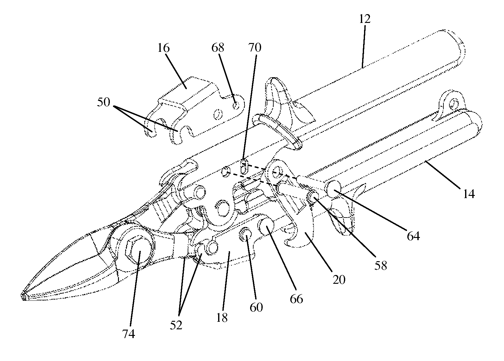
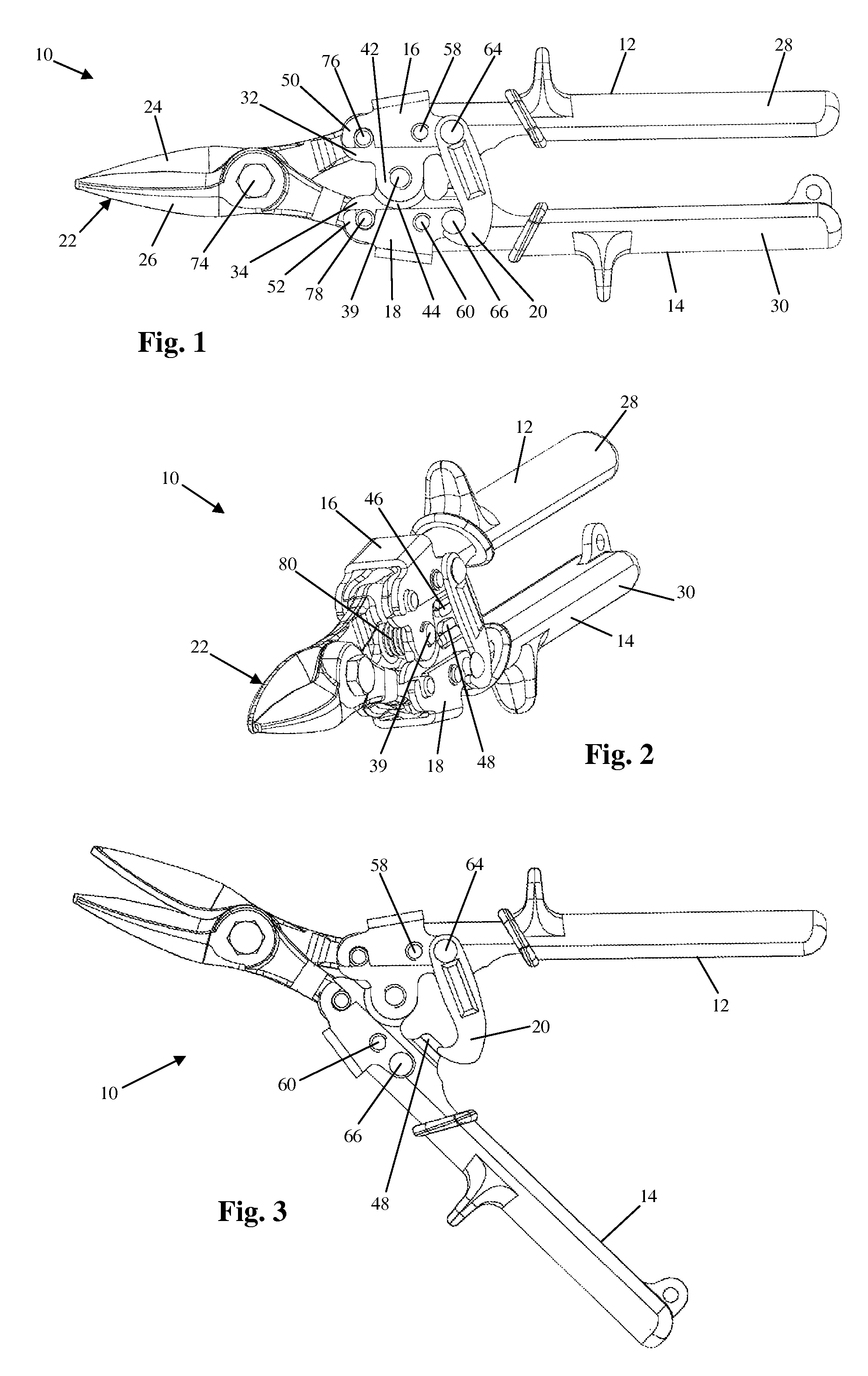
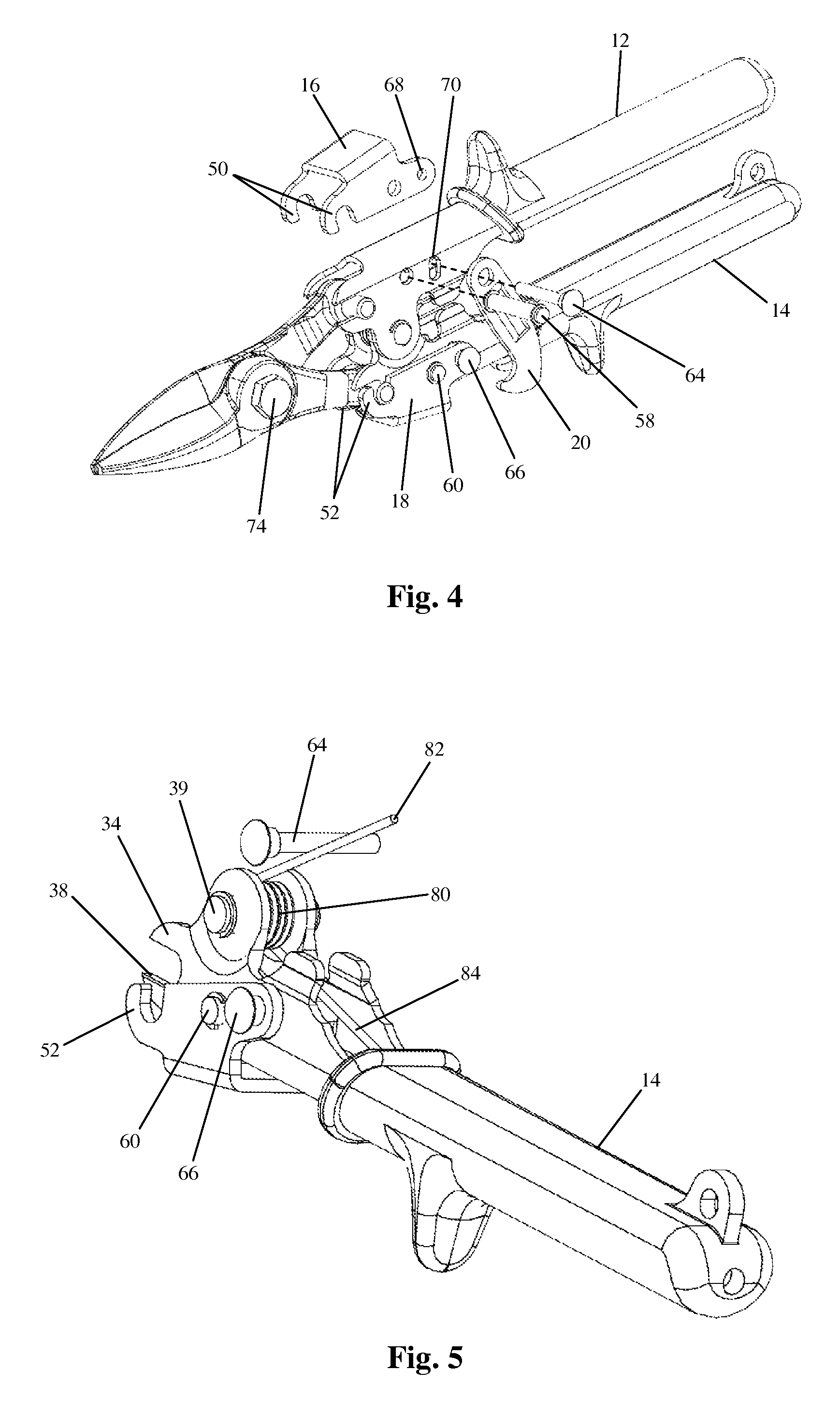
[0024]Referring to FIGS. 1-3, an illustrative embodiment of a compound leverage, interchangeable-tool head hand tool in accordance with the present invention is indicated generally by the numeral 10. Referring to FIGS. 1 and 2, the tool 10 generally includes two pivotably interconnected handles 12 and 14, two tool head latches 16 and 18, a handle latch 20, and a removable tool head 22, for example a pair of pivotably interconnected blades 24 and 26. Unless otherwise noted, all components of the tool 10 are formed of conventional steel of the type used to fabricate common hand tools, although it is contemplated that the tool 10 can be formed of any other suitably rigid and durable material(s), including, but not limited to high carbon steel and titanium.

[0025]Referring to FIGS. 1, 2 and 8, each of the handles 12 and 14 of the tool 10 terminates at a first end in a rubberized hand grip 28 and 30 and terminates at a second end in a pair of laterally spaced, U-shaped retention slots 36 ...


PUM

PropertyMeasurementUnit
forceaaaaaaaaaa
mechanical advantageaaaaaaaaaa
durableaaaaaaaaaa

Abstract

A compound leverage hand tool with an interchangeable tool head. The tool includes a pair of pivotably interconnected handles and a tool head defined by a pair of pivotably interconnected blade members. Each blade member terminates at one end in a mounting dowel that is pivotably mounted in a pair of retention slots in one of the handles. Tool head latches are pivotably mounted to the handles and include locking fingers that extend over the retention slots. The tool head latches can be pivoted relative to the handles between a locked position, wherein the locking fingers prevent the mounting dowels from being removed from the handles, and an unlocked position, wherein the mounting dowels can be removed from the handles. A spring biases the tool head latches toward the locked position. To unlock the tool head latches and remove the tool head, a user engages a tool head latch and pulls the handles apart.

Description

CROSS-REFERENCES TO RELATED APPLICATIONS[0001]This application claims the benefit of U.S. Provisional Application No. 61 / 285,057 filed Dec. 9, 2009.STATEMENT REGARDING FEDERALLY-SPONSORED RESEARCH AND DEVELOPMENT[0002](Not Applicable)REFERENCE TO AN APPENDIX[0003](Not Applicable)BACKGROUND OF THE INVENTION[0004]This invention relates generally to the field of hand tools and relates more particularly to a compound leverage hand tool with an interchangeable tool head.[0005]Compound leverage hand tools (also called “compound action” hand tools) generally include a pair of pivotally interconnected handles which are each also pivotally connected at one end to a tool head. The tool head includes a pair of pivotally interconnected workpiece engaging members, which can include snips blades, pliers jaws, seamer blades, clamps or the like. The manner in which the components of a compound leverage tool are pivotably linked to one another provides a user of the tool with a mechanical advantage ...

Claims


Application Information

Patent Timeline
Patent Type & Authority Patents(United States)
IPC IPC(8): B25B7/02
CPCA01G3/02B23D29/026B25B7/00B25B7/14B25F1/003B25F1/02B26B13/04B26B13/16B26B13/26
Inventor MUSSER, SCOTT
Owner MIDWEST TOOL & CUTLERY
Why Eureka
Try Eureka