Strap pipe wrench for driving an object having a generally cylindrical shape

a technology of a cylindrical shape and a strap pipe wrench, which is applied in the direction of power operated devices, applications, and opening closed containers, can solve the problems of repetitive and lengthy strap adjustment phases, and achieve the effect of facilitating the strap adjustmen

Active Publication Date: 2012-11-27
STANLEY BLACK & DECKER MEA FZE
View PDF10 Cites 7 Cited by
  • Summary
  • Abstract
  • Description
  • Claims
  • Application Information

AI Technical Summary

Benefits of technology

[0012]An object of the invention is to facilitate the adjustment of the strap in a particularly ergonomic manner.

Problems solved by technology

The phases of adjusting the strap are lengthy and repetitive.

Method used


Image

  • Strap pipe wrench for driving an object having a generally cylindrical shape
  • Strap pipe wrench for driving an object having a generally cylindrical shape
  • Strap pipe wrench for driving an object having a generally cylindrical shape

Examples


Embodiment Construction

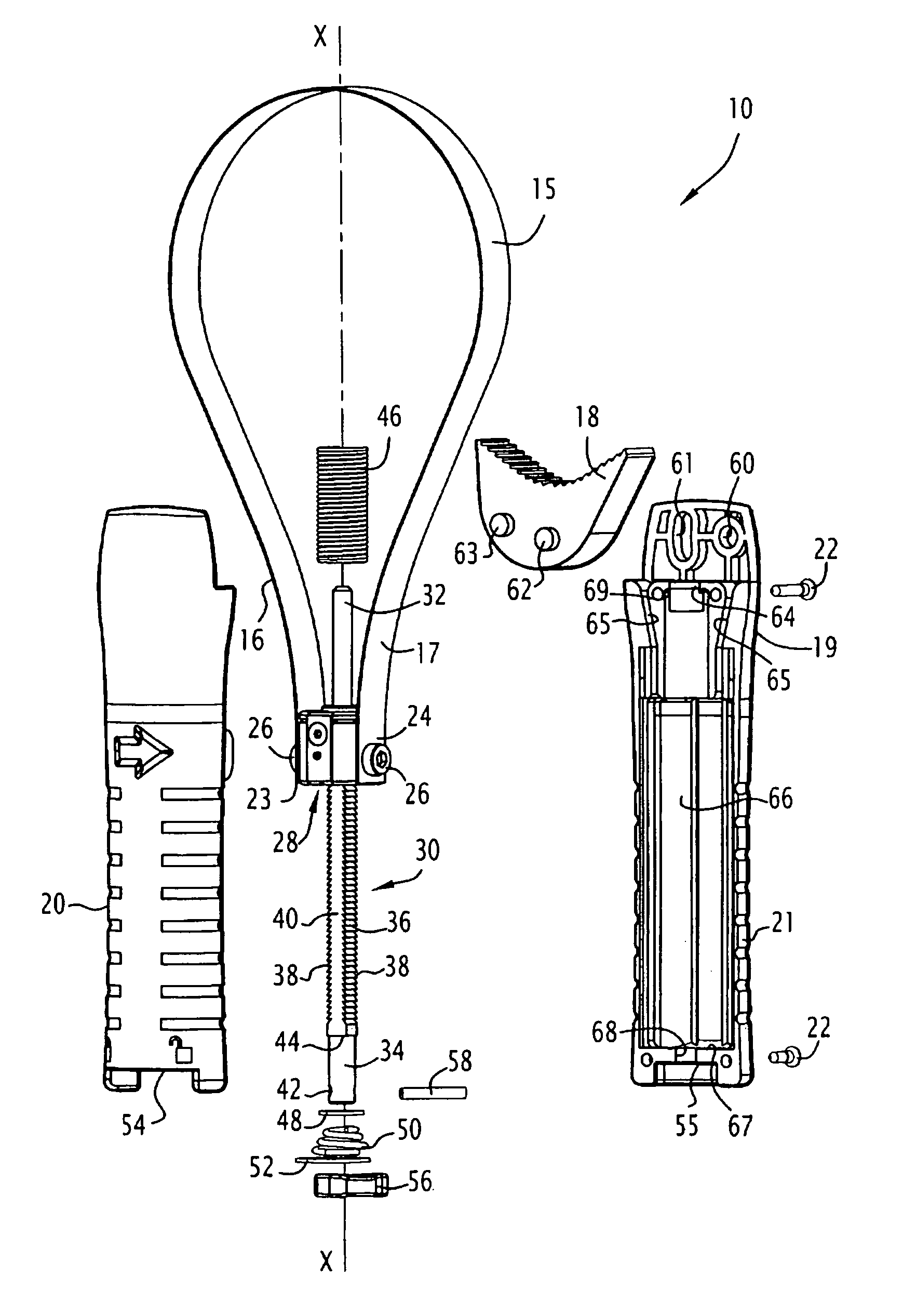
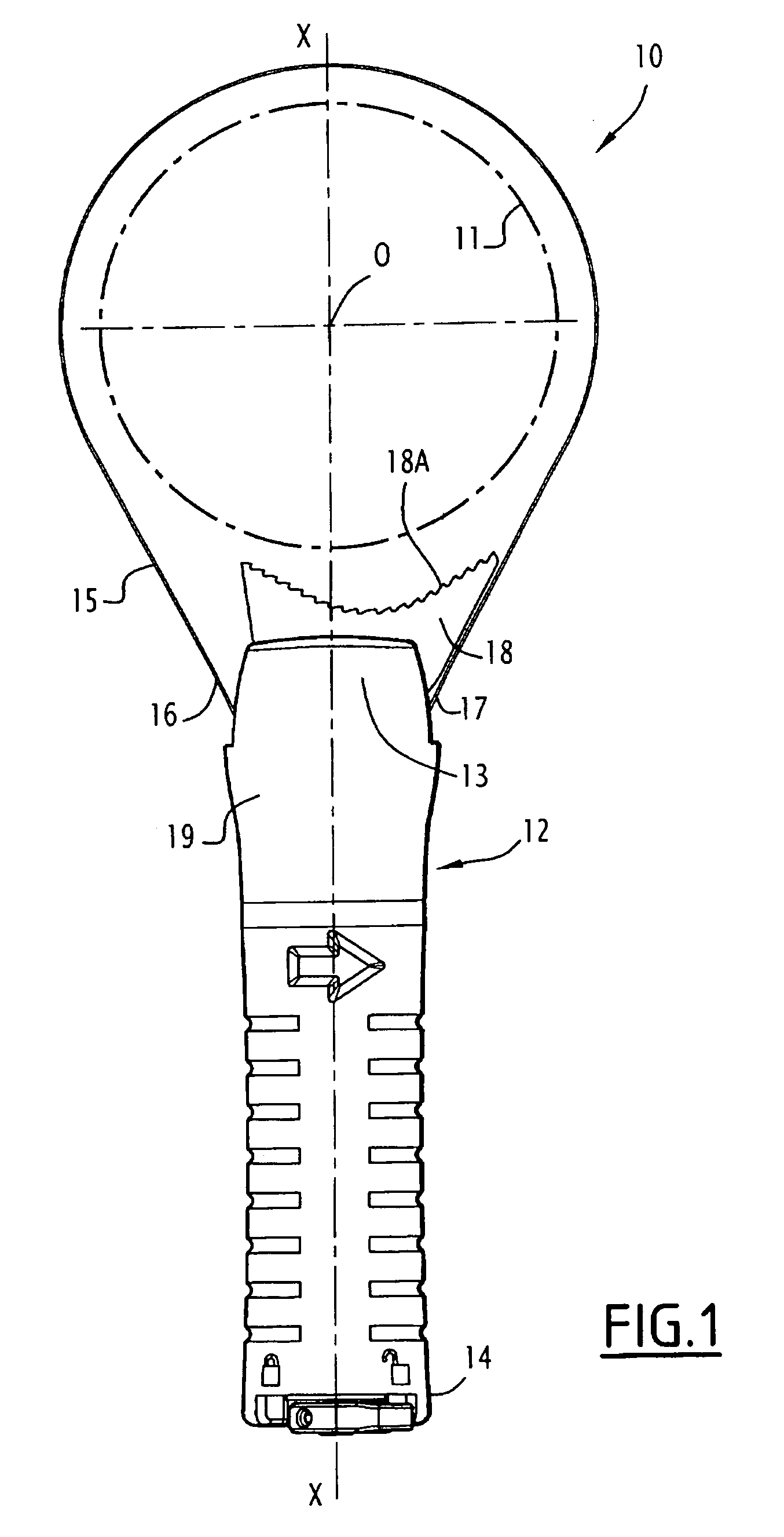
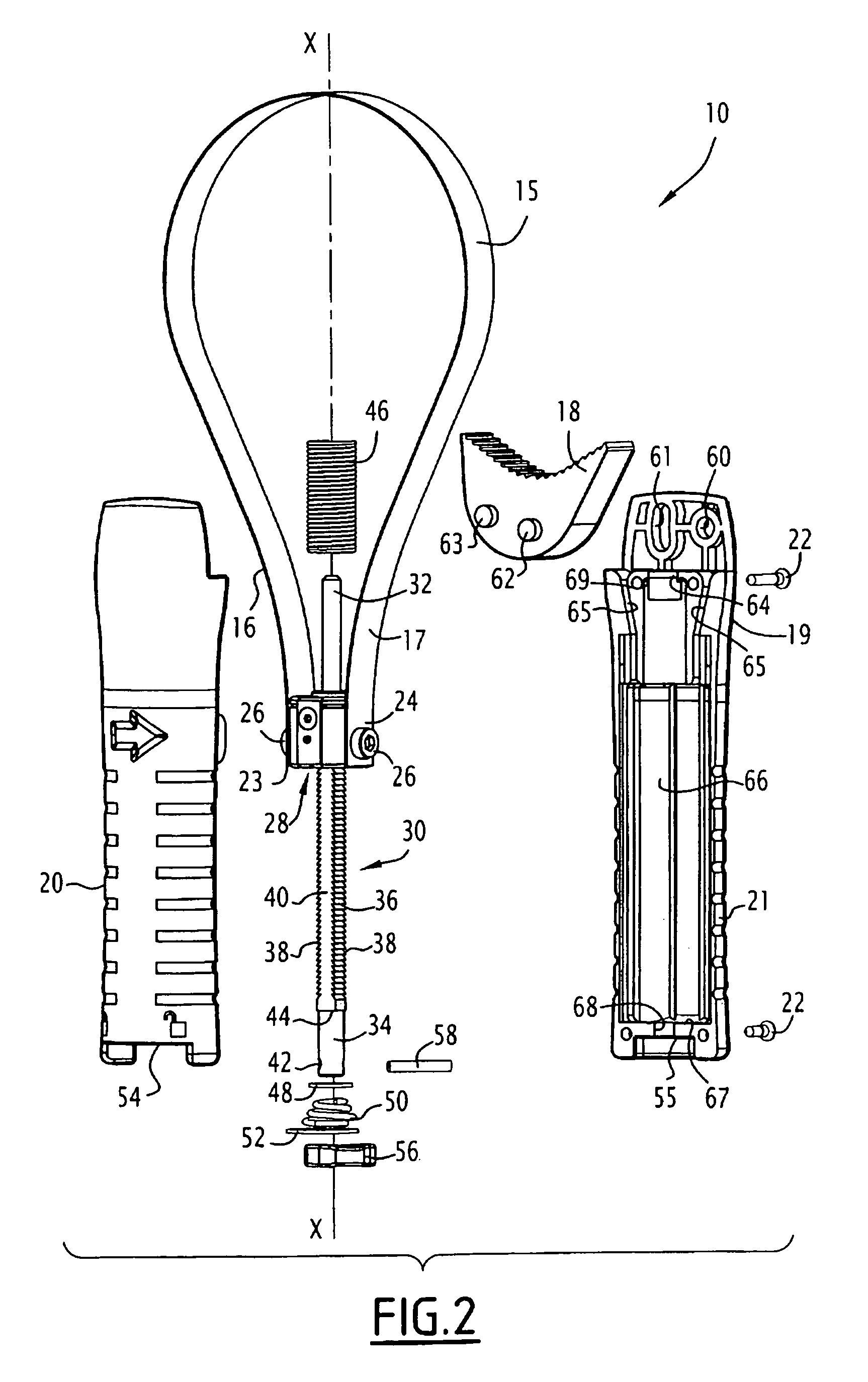
[0045]The strap pipe wrench 10 shown in FIGS. 1 to 12 is intended principally for unscrewing, and secondarily, by turning the wrench round, for screwing in, objects 11 having a generally cylindrical shape, especially oil filters, the diameters of which can vary within a wide range, for example, in the embodiment shown, from 64 to 106 mm.

[0046]In order to describe the wrench 10 more easily, it will be assumed to be oriented as shown in the drawings, extending according to a longitudinal axis X-X with the filter 11, of axis O, situated above the handle of the wrench.

[0047]In FIG. 1, the strap pipe wrench 10 comprises a handle 12 having a distal portion 13 that forms a cap, the sides of which are parallel to the plane of the drawing, and a proximal portion 14.

[0048]A band 15, especially a band made of metal and forming a strap in the form of a loop, has two end portions 16 and 17 which are connected to the handle 12. A shoe for abutment on the filter 11, having the reference numeral 18...


PUM


Abstract

A strap pipe wrench for driving an object having a generally cylindrical shape includes a handle which extends along a longitudinal axis, a connecting member which is movable relative to the handle in a direction parallel to the longitudinal axis, and a strap formed in a loop and having two opposing end portions which cooperate with two zones integral with the handle when the strap surrounds the object tightly, the two opposing end portions of the strap being attached to the connecting member, a displacement device for displacing said connecting member, and enabling the size of the loop of the strap to be adjusted and the strap to be tensioned when it surrounds the object tightly, and a shoe disposed between the two zones for abutment on the object, the shoe having an abutment face of generally arcuate shape.

Description

BACKGROUND OF THE INVENTION[0001](1) Field of the Invention[0002]The present invention relates to a strap pipe wrench for driving an object having a generally cylindrical shape, of the type comprising:[0003]a part forming a handle which extends according to a longitudinal axis;[0004]a strap, especially a metal strap, in loop form, the two opposing end portions of which cooperate with two zones integral with the handle when the strap surrounds said object tightly;[0005]a connecting member which is movable relative to the part forming a handle according to the longitudinal axis thereof, the two opposing end portions of the strap having ends that are integral with said member;[0006]means for displacing said connecting member, enabling the size of the loop of the strap to be adjusted and the strap to be tensioned when it surrounds said object tightly; and[0007]the part forming a handle being equipped, between said two zones, with a shoe for abutment on said object, the abutment shoe not...

Claims


Application Information

Patent Timeline
Patent Type & Authority Patents(United States)
IPC IPC(8): B25B13/52
CPCB25B13/52B25B27/0042B67B7/186
Inventor IDIR, HADI
Owner STANLEY BLACK & DECKER MEA FZE
Why Eureka
Try Eureka