Arrangement of tubing in solar boiler panels

a solar boiler and tubing technology, applied in solar heat systems, solar thermal energy generation, lighting and heating apparatus, etc., can solve the problems of new challenges in handling intense solar heat, and achieve the effect of reducing solar radiation and solar radiation

Active Publication Date: 2012-11-27
BABCOCK POWER SERVICES
View PDF154 Cites 0 Cited by
  • Summary
  • Abstract
  • Description
  • Claims
  • Application Information

AI Technical Summary

Benefits of technology

[0010]The subject invention is directed to a new and useful boiler for a solar receiver. The boiler includes a first boiler panel having a plurality of tubes fluidly connecting an inlet header of the first boiler panel to an outlet header of the first boiler panel. The tubes of the first boiler panel form a first solar receiver surface and a first internal surface opposite the first solar receiver surface. A second boiler panel has a plurality of tubes fluidly connecting an inlet header of the second boiler panel to an outlet header of the second boiler panel. The tubes of the second boiler panel form a second solar receiver surface and a second internal surface opposite the second solar receiver surface. The first and second boiler panels are adjacent to one another with a portion of the first boiler panel and an end of the first solar receiver surface overlapping an end of the second boiler panel to reduce solar radiation passing between the first and second solar receiver surfaces.
[0013]The invention also includes a boiler for a solar receiver including steam generator, superheater, and reheater panels, each having a plurality of tubes fluidly connecting a respective inlet header and a respective outlet header. The tubes of each panel form a solar receiver surface and opposed internal surface. The steam generator and superheater panels are adjacent one another with a portion of the steam generator panel and an end of the solar receiver surface thereof overlapping an end of the superheater panel to reduce solar radiation passing between the solar receiver surfaces of the steam generator and superheater panels. The steam generator and reheater panels are adjacent one another with a portion of the reheater panel including an end of the solar receiver surface thereof overlapping an end of the steam generator panel to reduce solar radiation passing between the solar receiver surfaces of the steam generator and reheater panels.

Problems solved by technology

This development has lead to new challenges in handling the intense solar heat without damage to the system.

Method used


Image

  • Arrangement of tubing in solar boiler panels
  • Arrangement of tubing in solar boiler panels
  • Arrangement of tubing in solar boiler panels

Examples


Embodiment Construction

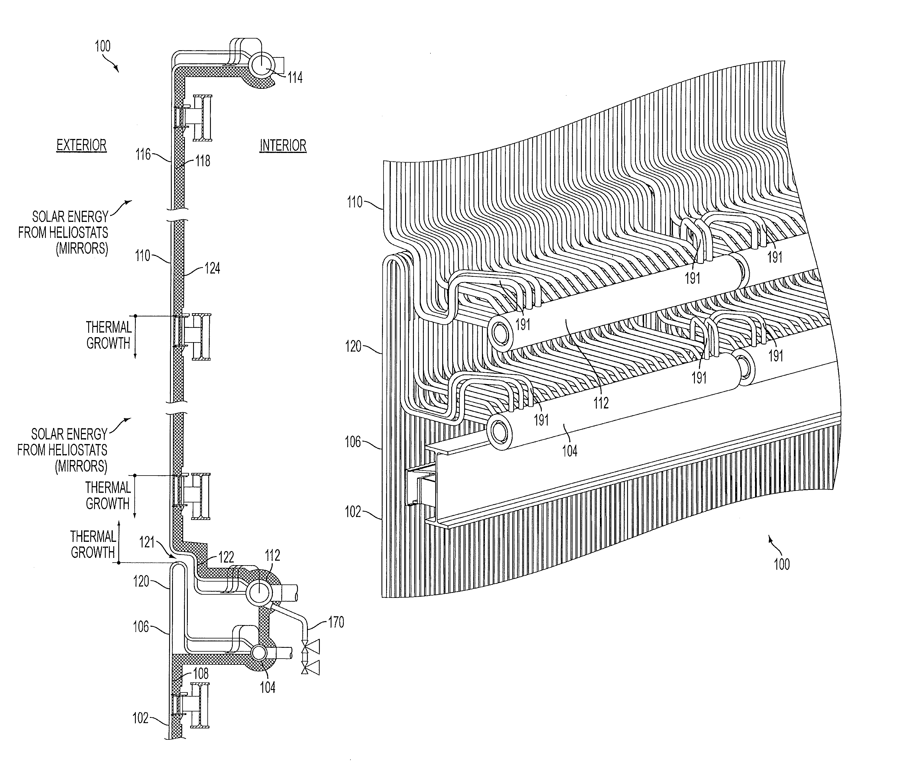
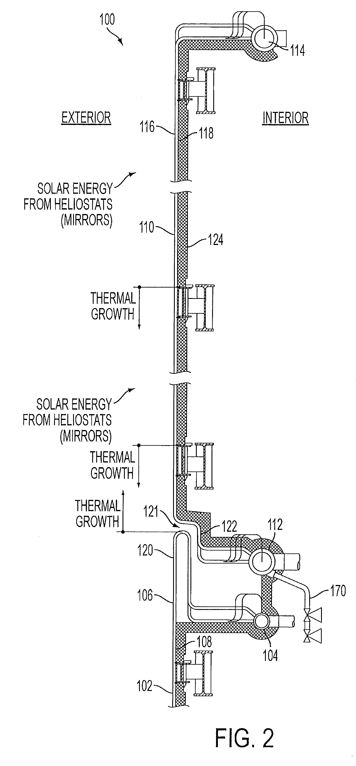
[0022]Reference will now be made to the drawings wherein like reference numerals identify similar structural features or aspects of the subject invention. For purposes of explanation and illustration, and not limitation, a partial view of an exemplary embodiment of a boiler constructed in accordance with the invention is shown in FIG. 2 and is designated generally by reference character 100. Other embodiments of a boiler in accordance with the invention, or aspects thereof, are provided in FIGS. 3-5, as will be described. The systems of the invention can be used to increase the effective receiving area while protecting internal spaces and components in boilers, for example in solar power generation.

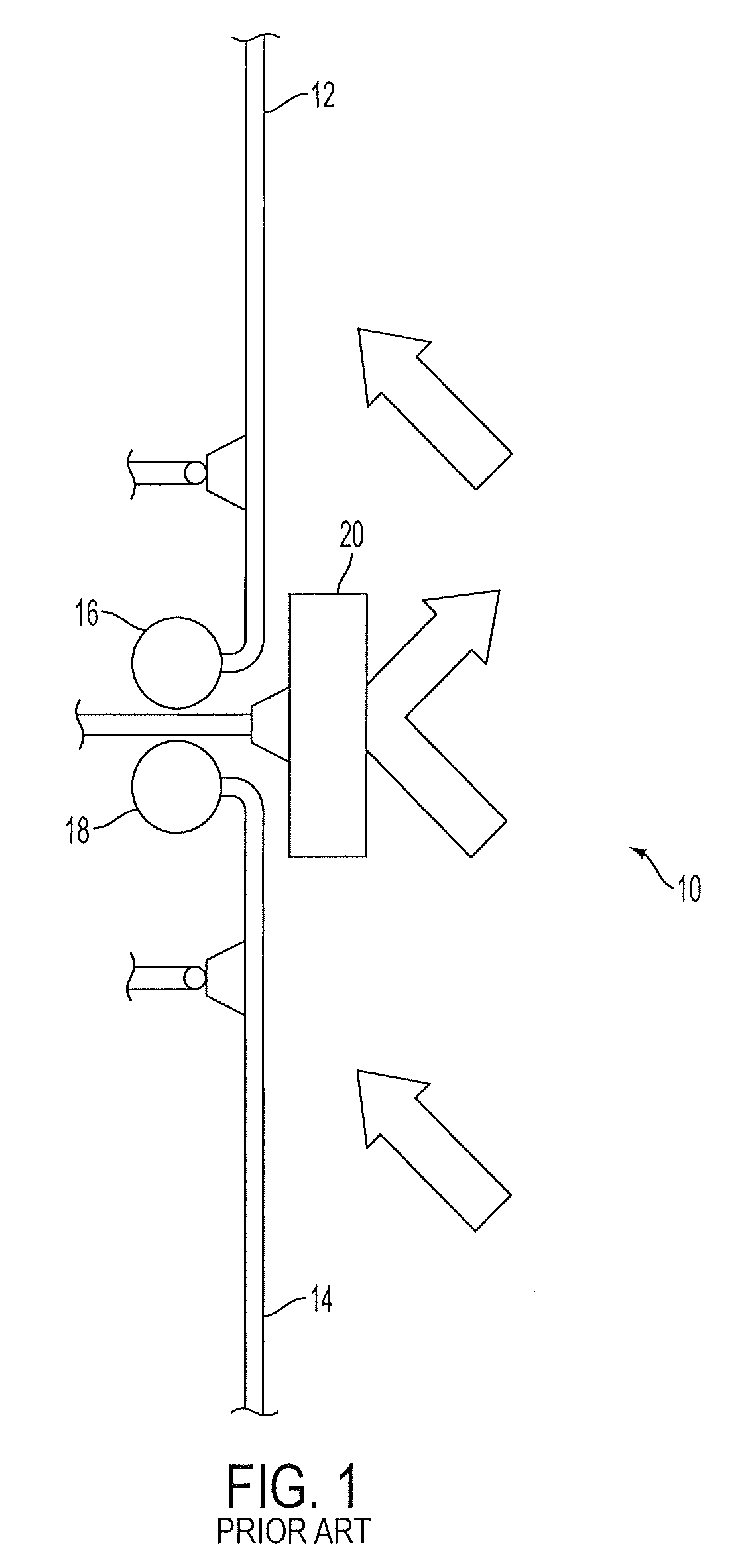
[0023]Solar boilers are set up in such a way that there are at least two distinct tube sections: one is a steam generator section containing boiling water and one or more is a superheating section containing superheated steam. FIG. 1 shows an example of a solar boiler 10 having a steam ge...


PUM


Abstract

A boiler for a solar receiver includes a first boiler panel having a plurality of tubes fluidly connecting an inlet header of the first boiler panel to an outlet header of the first boiler panel. The tubes of the first boiler panel form a first solar receiver surface. A second boiler panel has a plurality of tubes fluidly connecting an inlet header of the second boiler panel to an outlet header of the second boiler panel. The tubes of the second boiler panel form a second solar receiver surface. The first and second boiler panels are adjacent to one another with a portion of the first boiler panel and an end of the first solar receiver surface overlapping an end of the second boiler panel to reduce solar radiation passing between the first and second solar receiver surfaces.

Description

CROSS-REFERENCE TO RELATED APPLICATIONS[0001]This application claims priority to U.S. Provisional application No. 61 / 151,984, filed Feb. 12, 2009, to U.S. Provisional application No. 61 / 152,011, filed Feb. 12, 2009, to U.S. Provisional application No. 61 / 152,035, filed Feb. 12, 2009, to U.S. Provisional application No. 61 / 152,049, filed Feb. 12, 2009, to U.S. Provisional application No. 61 / 152,077, filed Feb. 12, 2009, to U.S. Provisional application No. 61 / 152,114, filed Feb. 12, 2009, and to U.S. Provisional application No. 61 / 152,286, filed Feb. 13, 2009, each of which is incorporated by reference herein in its entirety.BACKGROUND OF THE INVENTION[0002]1. Field of the Invention[0003]The present invention relates to solar power production, and more particularly, to solar receiver panels for use in solar boilers.[0004]2. Description of Related Art[0005]Solar power generation has been considered a viable source to help provide for energy needs in a time of increasing consciousness o...

Claims


Application Information

Patent Timeline
Patent Type & Authority Patents(United States)
IPC IPC(8): F24J2/46F24S10/30F24S10/70F24S20/20
CPCF24J2/07F24J2/245Y02E10/44Y02E10/41F24S20/20F24S10/742Y02E10/40
Inventor PLOTKIN, ANDREWTOUPIN, KEVINRICCI, RUSSELL
Owner BABCOCK POWER SERVICES
Why Eureka
Try Eureka