Bicycle seat height adjusting assembly

a seat height and assembly technology, applied in the field of seat posts, can solve the problems of limited range, dangerously loose control of cyclists, and most of these designs are not capable of full adjustment, and achieve the effects of not quickly wear out or cause even greater damage to the seat post, high durability, and even spring ra

Active Publication Date: 2012-11-27
WALSH AUSTIN A
View PDF16 Cites 99 Cited by
  • Summary
  • Abstract
  • Description
  • Claims
  • Application Information

AI Technical Summary

Benefits of technology

[0012]An object and advantage of the present invention is a seat post assembly that uses a counter rotational assembly for the seat post that does not allow the seat post to have any side to side play, whatsoever. The counter rotational device should slide well and not have enough friction as to bind when being used as this would halt the seat posts operation. The counter rotational device should also be highly durable as not to quickly wear out or cause even greater damage to the main post.
[0013]An object and advantage of the present invention is a seat post assembly that does not have any perforations or locking holes on the exterior surface of the seat post, to avoid any dirt from being brought into the locking or telescoping system where any dirt might cause scratching of the post or impeding of the lock system.
[0014]An object and advantage of the present invention is a seat post assembly that has a main inverted air spring that is positioned within the seat post to keep the air spring sealed and free from being impeded by dirt, which there is much of, often when mountain biking.
[0015]Another object and advantage of the present invention is a seat post assembly that incorporates a full span air spring design that is able to maintain a very even spring rate while fully rising and fully lowering.
[0016]Another object and advantage of the present invention is a seat post assembly containing this inverted, two chamber air spring design that further enables the use of a lightweight air dampening system that keeps the seat post from rising up too fast.
[0017]Another object and advantage of the present invention is a seat post assembly that utilizes a main air spring to provide a strong and lightweight adjusting seat post due to its high strength and lightweight tubular type structure.

Problems solved by technology

Yet, most of these designs are not capable of full adjustment as they are limited in their range of operation by the type of main spring that is used in combination with a locking system that often gets in the way by requiring much of the room inside of the seat post.
A seat post adjusting system that requires the cyclist to remove one hand from the handlebars while riding over bumpy terrain would possibly cause the cyclist to dangerously loose control of the bicycle.
Height adjusting seat posts with any exposed perforations or lock openings positioned on it would increase the likelihood of dirt clogging the main locking system and further bringing dirt between the telescoping pieces.
Yet, the adjusting seat posts presented so far, all do not provide a fully capable, adjusting seat post.
These previous designs are extremely sensitive to dirt, as their air seals can be broken by any dirt that gets onto the seat post and is then lowered into the main insert sleeve.
All these other systems, also do not include a lightweight air dampening system or have the capacity to access a personally adjustable maximum height set system for achieving a full span of height adjustment.
Having the cable extend from the top of the moving seat post to the top tube of the bicycle frame, where it is first attached to the bike, creates a hazardous situation where the cable loosely dangles and may get caught on a piece of the bike or onto the rider to accidentally trigger the upward release of the seat post.
Such an unexpected release of the seat post could be very dangerous while riding down steep and bumpy terrain.
The counter rotational device should slide well and not have enough friction as to bind when being used as this would halt the seat posts operation.

Method used


Image

  • Bicycle seat height adjusting assembly
  • Bicycle seat height adjusting assembly
  • Bicycle seat height adjusting assembly

Examples


Embodiment Construction

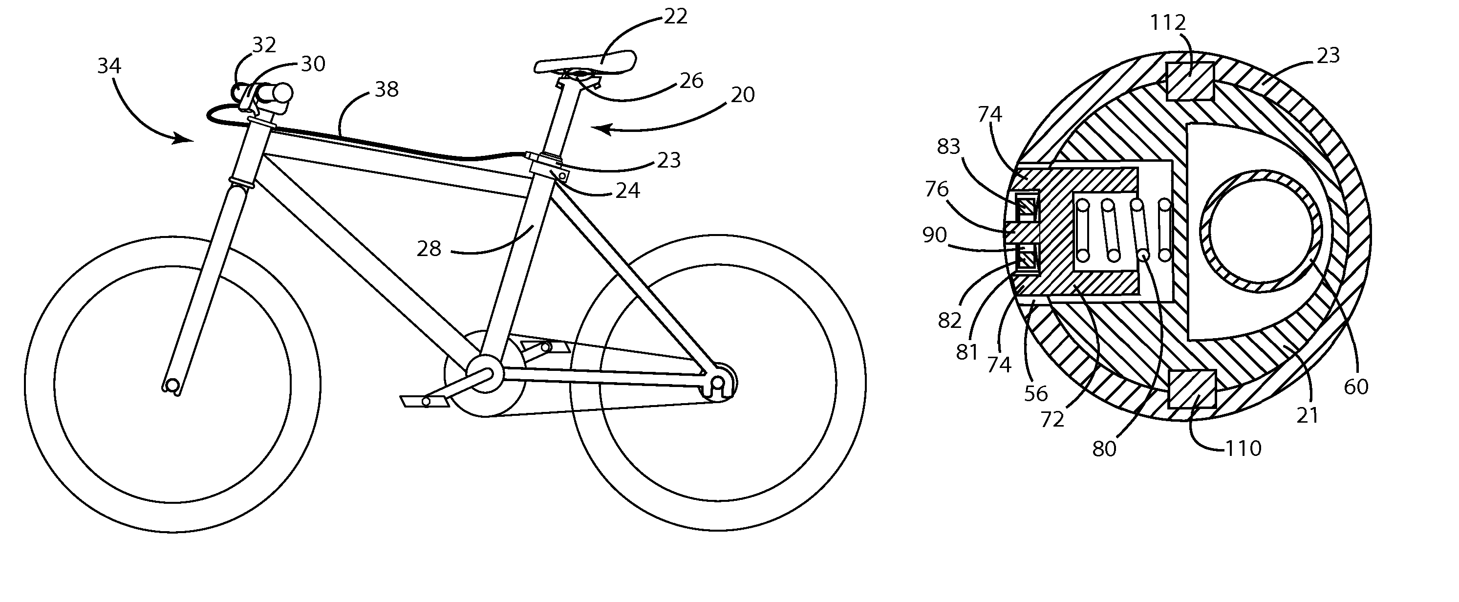
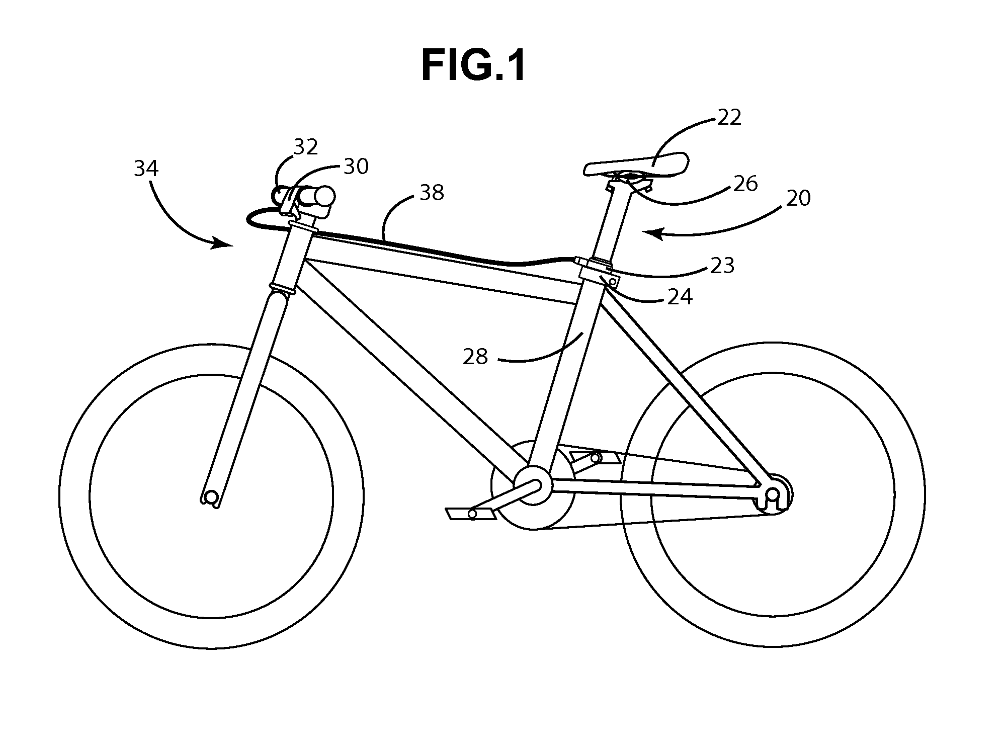
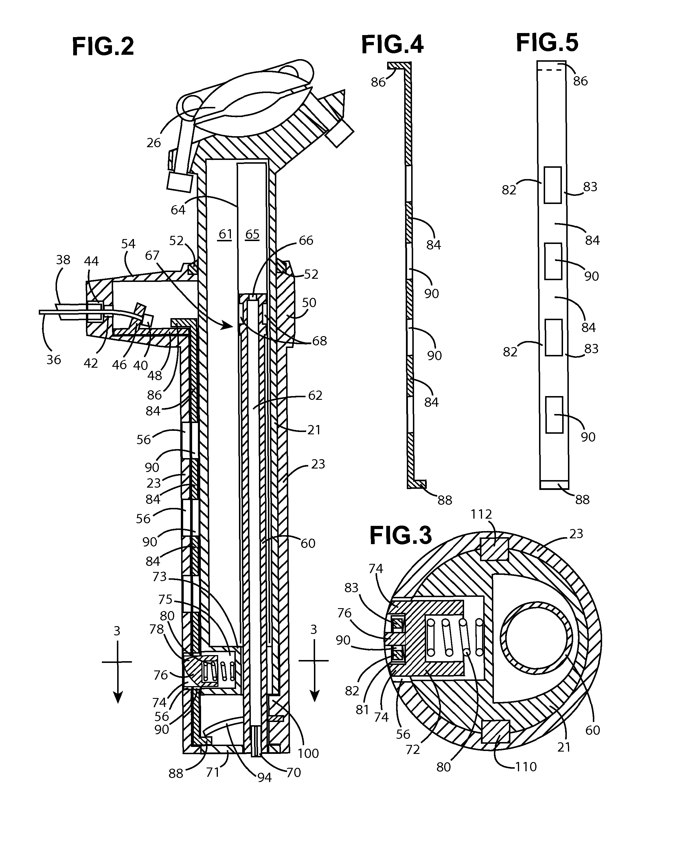
[0041]Referring now to the embodiment of the invention shown in FIG. 1, a new bicycle seat height adjusting assembly is presented and generally designated by the reference number 20. The seat height adjusting assembly 20 generally comprises a seat post 21 that is positioned within an insert tube 23. The insert tube 23 is shown inserted into the seat tube 28 of a bicycle frame 34. The insert tube 23 retrofits into the bicycle seat tube 28 in the place of a traditional seat post. The seat post 21 is adjustable up and down, being telescopically slidable within the insert tube 23. A cable housing 38 is shown extending outwardly from the upper portion of the insert tube 49. The cable housing is further connected to an actuation lever 15 that is positioned on the bicycle handlebar 32. The seat 22 is clamped to the top portion of the seat post 21 through any conventional clamping method 26. A post clamp 24 is positioned around the seat tube 28 of the bicycle frame 34 for fixedly securing t...


PUM


Abstract

A bicycle seat height adjusting assembly comprises of a seat post that axially slides into an insert tube that fits into a bicycle frame in the place of a conventional seat post. The front of the insert tube has a plurality of evenly spaced locking holes sized to receive a locking pin. The locking pin with supplemental spring is positioned within the lower section of the seat post. A main air spring is positioned within the seat post to keep the main air spring free from dirt interference, allow the post to fully rise and lower, and enable the use of a maximum height pre-adjustment system. A first longitudinal groove positioned along the inner wall of the insert tube contains a spline rod with wedging projections. The spline rod is connected to a cable that extends out to an actuation lever that is positioned on the handlebars. As the actuation lever is pulled, the wedging projections push the locking pin out of the locking holes where the main air spring causes the seat post to rise.

Description

[0001]This application claims the benefit of provisional application No. 61 / 409,895, filed Nov. 3, 2010.BACKGROUND OF THE INVENTION[0002]This invention relates generally to a seat post that can be fully raised or lowered, particularly on a mountain bicycle while the cycle is in motion.[0003]While a bicycle seat is positioned higher, the seated cyclist is able to exert a greater amount of force on the pedals. Yet, the bicycle is vastly more maneuverable while the seat is fully down and out of the way. While riding on trails that are steep and challengingly bumpy, this lower seat position gives the cyclist a lower center of gravity, to avoid being thrown off the bike. An adjusting seat post assembly should therefore have the capacity to be fully lowering and fully adjusting.[0004]There are a number of height adjusting seat post designs that provide an upwardly urging spring mechanism and a post locking means. Yet, most of these designs are not capable of full adjustment as they are li...

Claims


Application Information

Patent Timeline
Patent Type & Authority Patents(United States)
IPC IPC(8): B62J1/00B62J1/02
CPCB62J1/10B62K19/36B62J2001/085B62J1/08
Inventor WALSH, AUSTIN A.
Owner WALSH AUSTIN A
Why Eureka
Try Eureka