

Modular LED lighting system
a module-based, led-lighting technology, applied in the field of module-based led-lighting systems, can solve the problems of varying costs and lifespans of different components of led-lighting systems, limited lifespan of leds as a whole, and the fact that leds themselves might have virtually unlimited lifespans
- Summary
- Abstract
- Description
- Claims
- Application Information
AI Technical Summary
Benefits of technology
Problems solved by technology
Method used
Image

Examples
Embodiment Construction
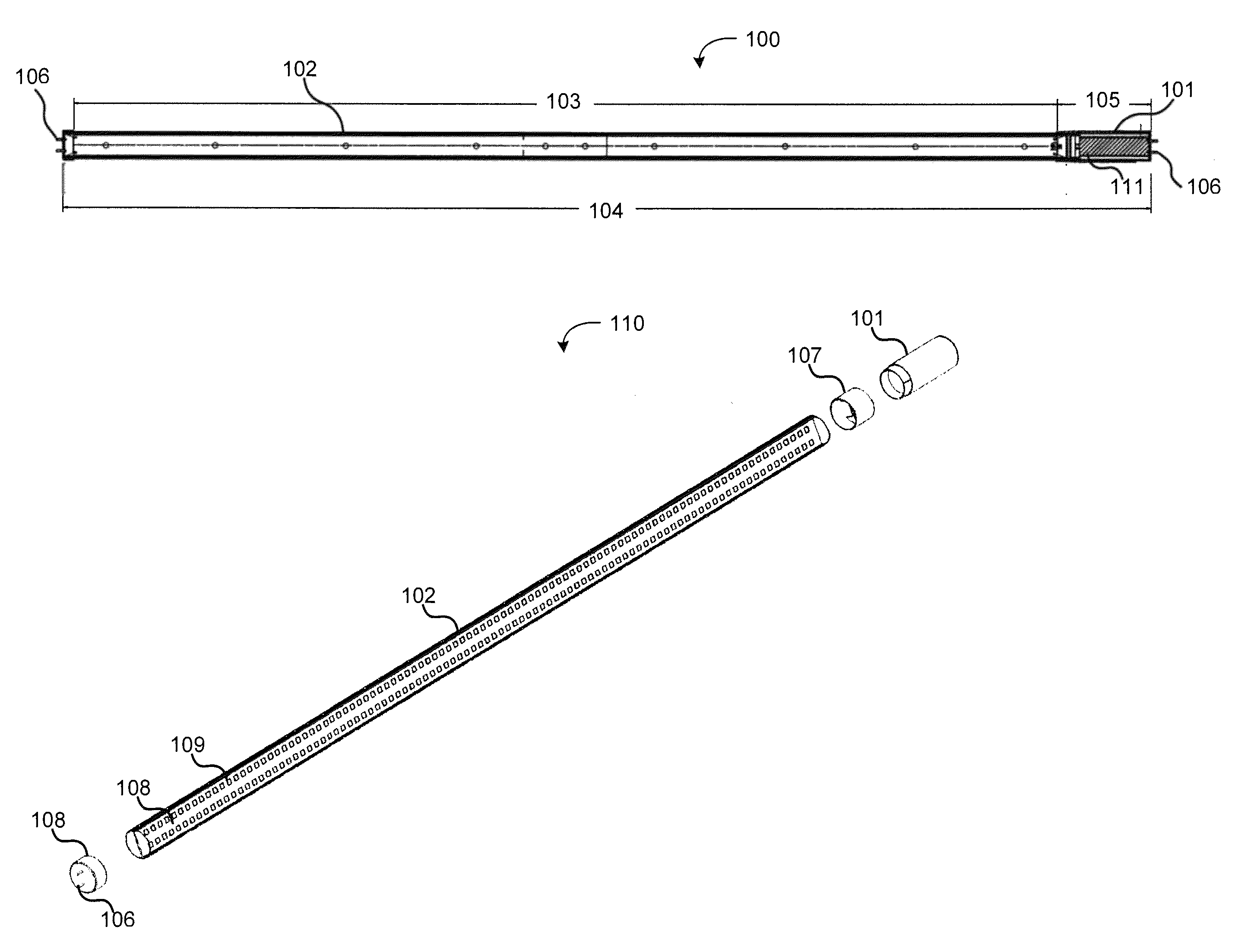
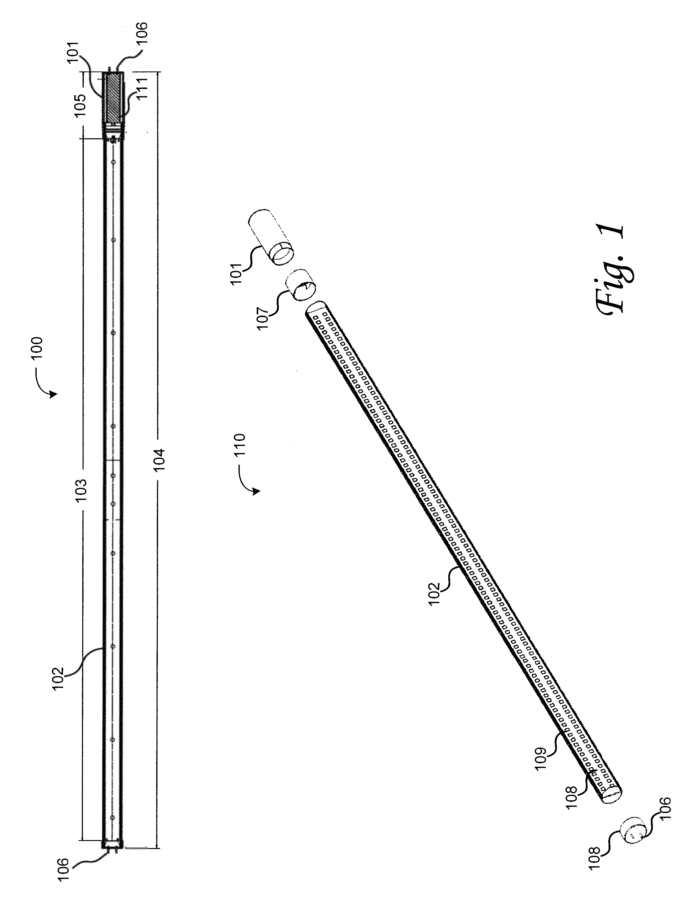
[0005]According to various embodiments of the invention, an LED lighting system is providing having a replaceable driver module. In some embodiments, the replaceable driver module comprises a component that is physically attachable to an LED illumination module, such that the attached components have a combined physical profile dimensioned for installation in a pre-existing light fixture. In further embodiments, the combined system's dimensions allow it to be installed in pre-existing fluorescent fixtures without requiring rewiring the fixtures. In some embodiments, the LED driver module may be configured to condition power received from a fluorescent light ballast to drive the LEDs such that a pre-existing fluorescent ballast does not need to be removed. In other embodiments, the LED driver may be configured to condition main power such that a pre-existing fluorescent ballast may be removed.
[0006]According to an embodiment of the invention, a modular lighting system comprises an il...
PUM
 Abstract
Description
Claims
Application Information