Non-linear optical grating

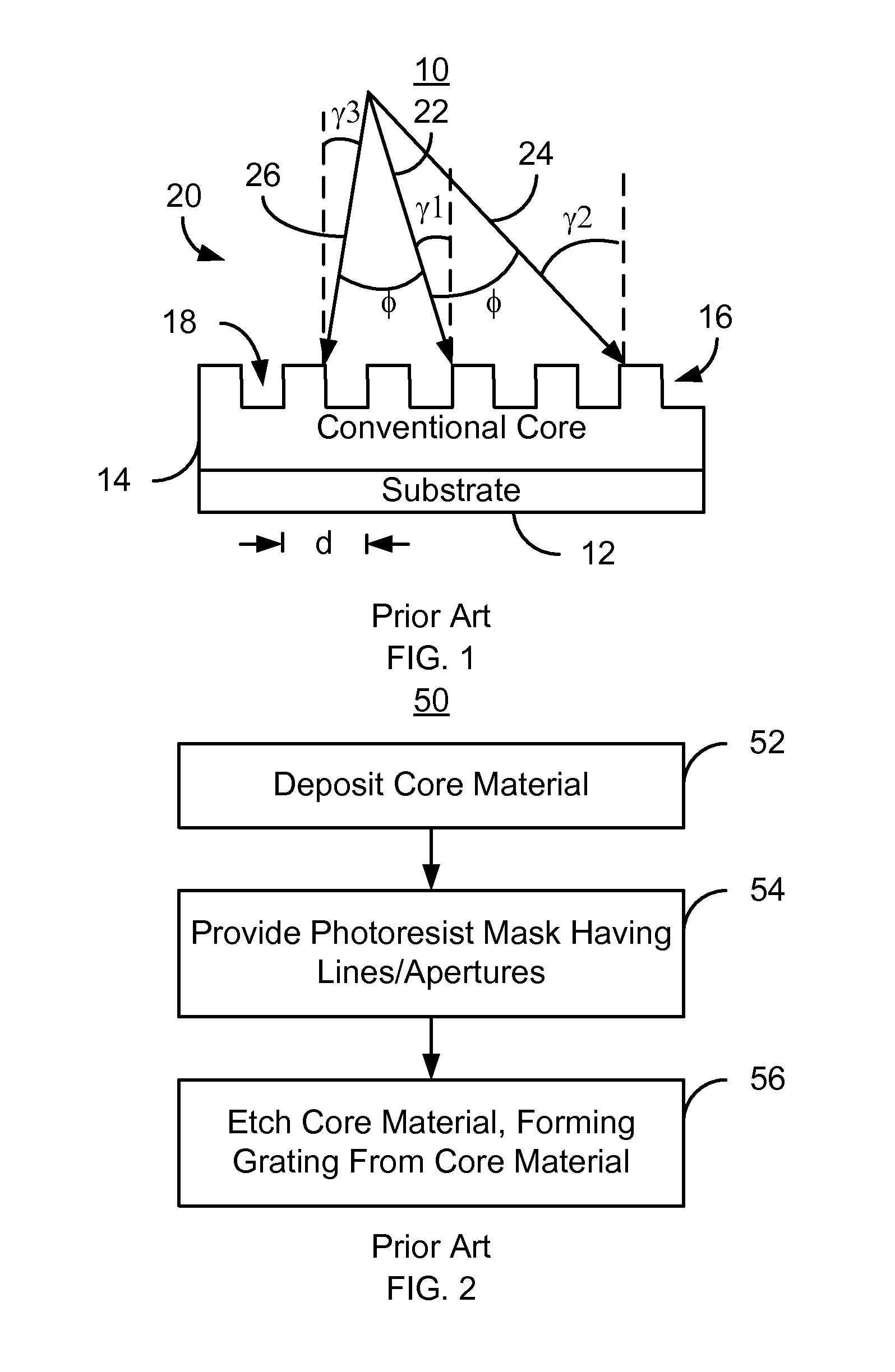
a non-linear optical grating and optical grating technology, applied in the field of non-linear optical grating, can solve the problems of affecting the ability to configure the conventional grating, the layer is not depicted for simplicity, and the conventional method b>50/b> may be limited in its ability to provide the desired conventional grating,

Active Publication Date: 2012-11-27
WESTERN DIGITAL TECH INC
View PDF17 Cites 151 Cited by
  • Summary
  • Abstract
  • Description
  • Claims
  • Application Information

AI Technical Summary

Problems solved by technology

However, such layers are not depicted for simplicity.
Further, the conventional method 50 may be limited in its ability to provide the desired conventional

Method used


Image

  • Non-linear optical grating
  • Non-linear optical grating
  • Non-linear optical grating

Examples


Embodiment Construction

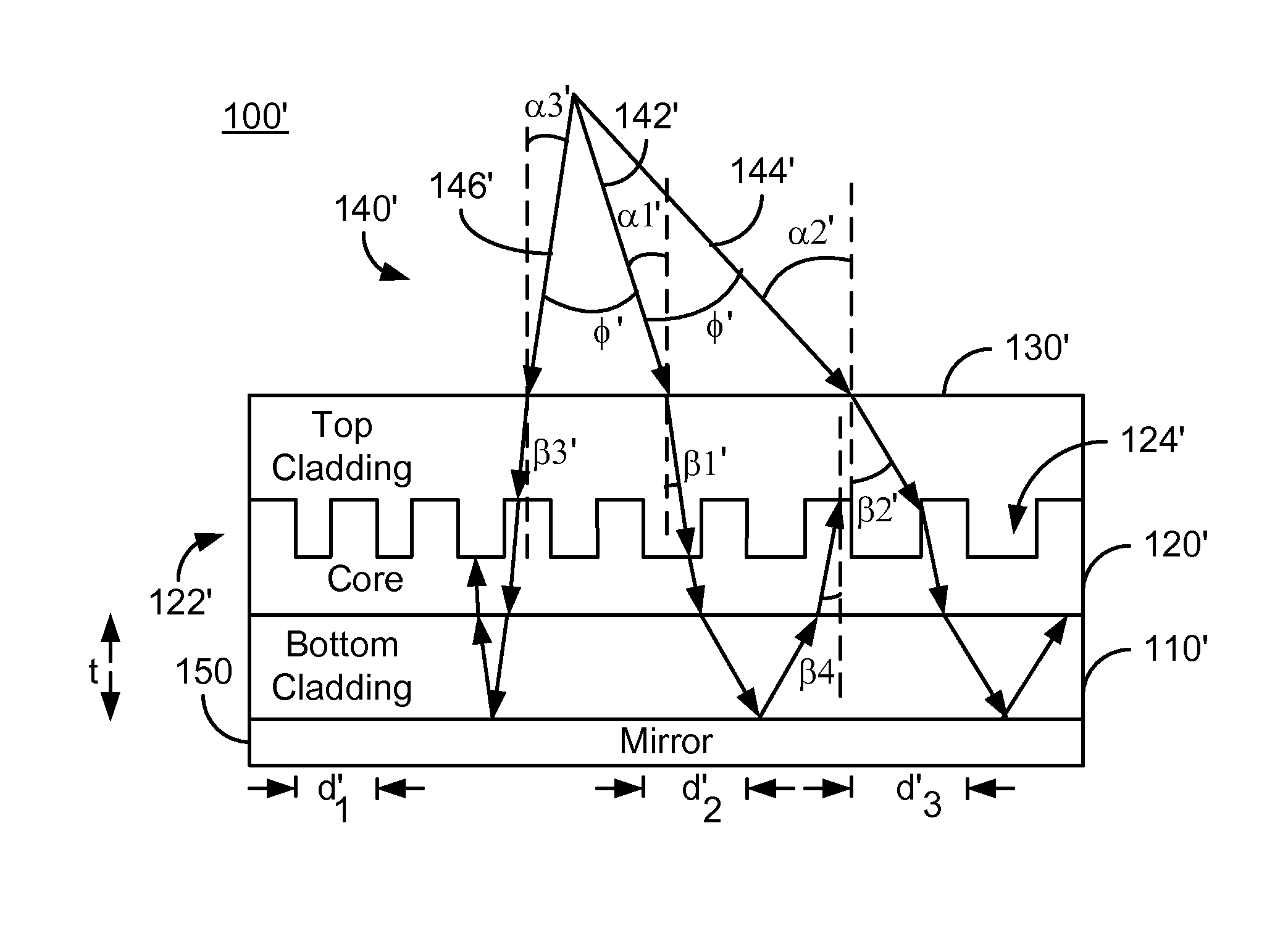
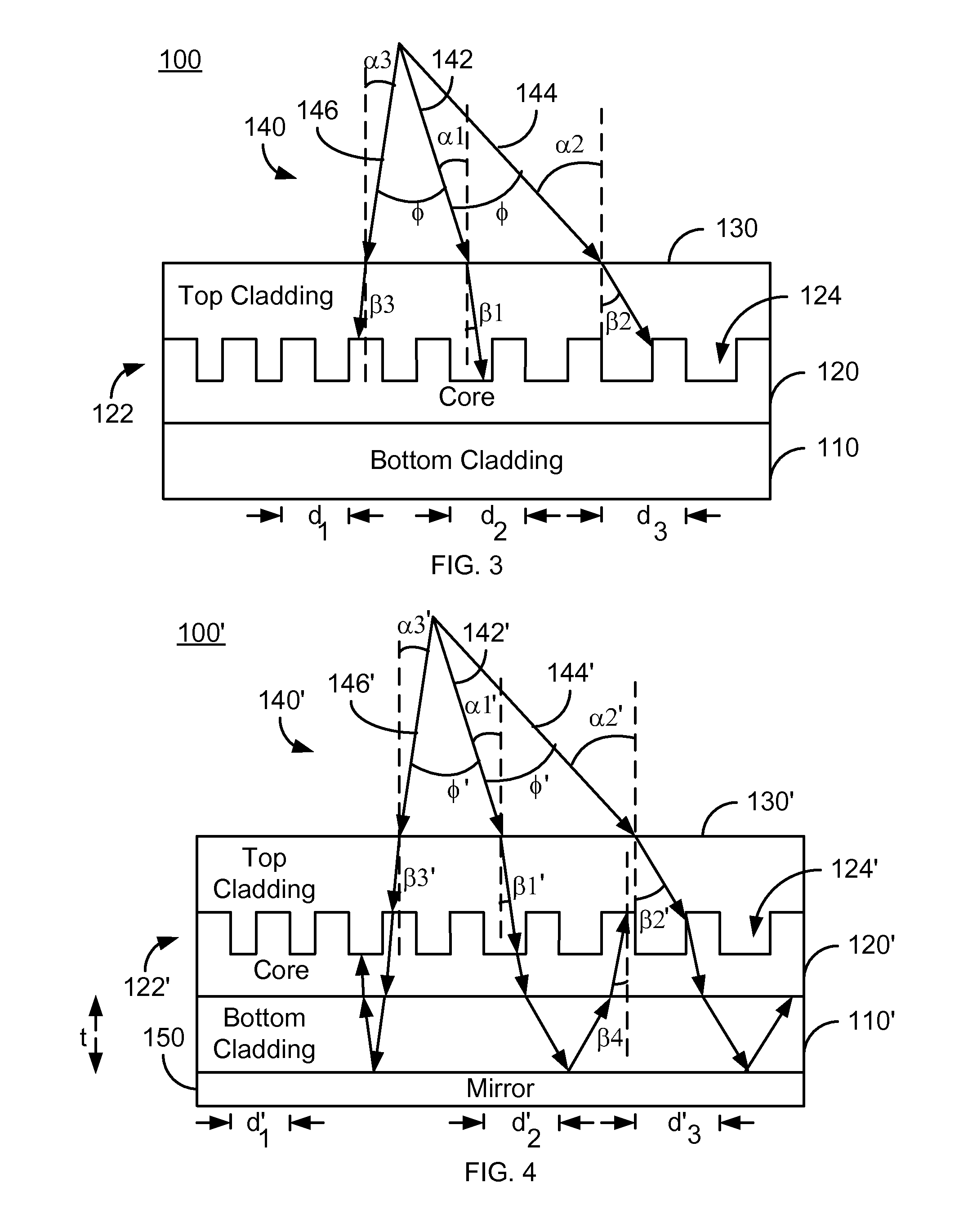
[0015]FIG. 3 is a diagram depicting an exemplary embodiment of an optical grating 100. FIG. 3 is not to scale. The optical grating 100 may be used in an EAMR head. For example, the optical grating 100 may be incorporated into the optics of an EAMR write transducer. However, in other embodiments, the optical grating 100 may be used in another application. The optical grating 100 includes a bottom cladding layer 110, a core 120, and a top cladding layer 130. The cladding 110 and 130 and the core 120 are desired to transmit light 140. However, the indices of refraction of the cladding layers 110 and 130 differ from the index of refraction of the core 120. Further, in some embodiments, the index of refraction of the bottom cladding 110 is the same as the top cladding 130. In such embodiments, the bottom cladding 110 and top cladding 130 may be composed of the same material, such as Al2O3. However, in other embodiments, the bottom cladding 110 and top cladding 130 may include different m...


PUM


Abstract

A method and system for providing an optical grating are described. The optical grating is configured for light of a wavelength. The optical grating includes a top cladding, a core, and bottom cladding. The core resides between the bottom cladding and the top cladding. The core includes a plurality of discrete ridges spaced apart by a nonlinear pitch. The light traverses the top cladding before the core and has a plurality of angles of incidence with the core. The nonlinear pitch of the core is larger for a larger angle of incidence of the plurality of angles of incidence.

Description

BACKGROUND[0001]Optical gratings are used for light coupling and delivery in a variety of optical systems. For example, in energy assisted magnetic recording (EAMR) electromagnetic radiation (light) is provided from a laser to a conventional grating. Typically, the light provided from the laser is in the optical range of the spectrum. The conventional grating is configured for a particular wavelength in the spectrum. Typically this means that the conventional grating actually functions in a range of wavelengths around the particular wavelength. The conventional grating couples light of the particular wavelength from the laser to a waveguide. The light from the waveguide is typically provided to a near-field transducer (NFT) and used to heat a spot on a magnetic recording media. Data is magnetically written to the spot while the spot is heated.[0002]FIG. 1 depicts such a conventional grating 10 formed on a substrate 12. The conventional grating 10 may be used in magnetic recording ap...

Claims


Application Information

Patent Timeline
IPC IPC(8): G02B6/34G02F1/295
CPCG02B6/124G02B5/1861
Inventor YUAN, HONGXINGLEE, SHINGWANG, ZHONGYANLI, JINSHAN
Owner WESTERN DIGITAL TECH INC
Why Eureka
Try Eureka