
System decomposition via evolutionary programming

a technology of evolutionary programming and system decomposition, applied in the field of optimization, can solve the problems of increasing the complexity of determining the quality of candidate decompositions, no known polynomial-time solutions,

Inactive Publication Date: 2012-11-27
LOCKHEED MARTIN CORP
View PDF3 Cites 0 Cited by
  • Summary
  • Abstract
  • Description
  • Claims
  • Application Information

AI Technical Summary

Benefits of technology

The present invention provides a technique for generating good system decompositions using evolutionary programming. This involves using reproductive operators to modify the structure of computer programs or data structures and evaluate their fitness. The process is repeated until a high degree of coherence is achieved. The invention is advantageous in that it can be implemented using an existing evolutionary programming engine and utilizes the symbol-processing capabilities of this technique. The technical effect of the invention is the efficient and effective generation of high-quality system decompositions.

Problems solved by technology

Such problems have no known polynomial-time solutions and are considered intractable for anything other than small problem sizes (i.e., in the case of system decomposition, systems with a small number of elements).
Moreover, for typical large system design problems there are often additional system-subsystem decomposition criteria that must be considered beyond coherence and coupling.
Adding these additional criteria significantly increases the complexity of determining the quality of candidate decompositions.

Method used


Image

  • System decomposition via evolutionary programming
  • System decomposition via evolutionary programming
  • System decomposition via evolutionary programming

Examples


Embodiment Construction

[0019]FIG. 3 depicts the salient elements of data-processing system 300, in accordance with the illustrative embodiment of the present invention. As shown in FIG. 3, data-processing system 300 comprises memory 301 and processor 302, interconnected as shown.

[0020]Memory 301 is capable of storing data and executable instructions, as is well-known in the art, and might be any combination of random-access memory (RAM), flash memory, disk drive memory, etc. It will be clear to those skilled in the art, after reading this specification, how to make and use memory 301.

[0021]Processor 302 is a general-purpose processor that is capable of executing instructions stored in memory 301, of reading data from and writing data into memory 301, and of executing the tasks of the methods described below and with respect to FIGS. 4 and 6. As will be appreciated by those skilled in the art, in some alternative embodiments of the present invention, processor 302 might instead be a special-purpose process...


PUM


Abstract

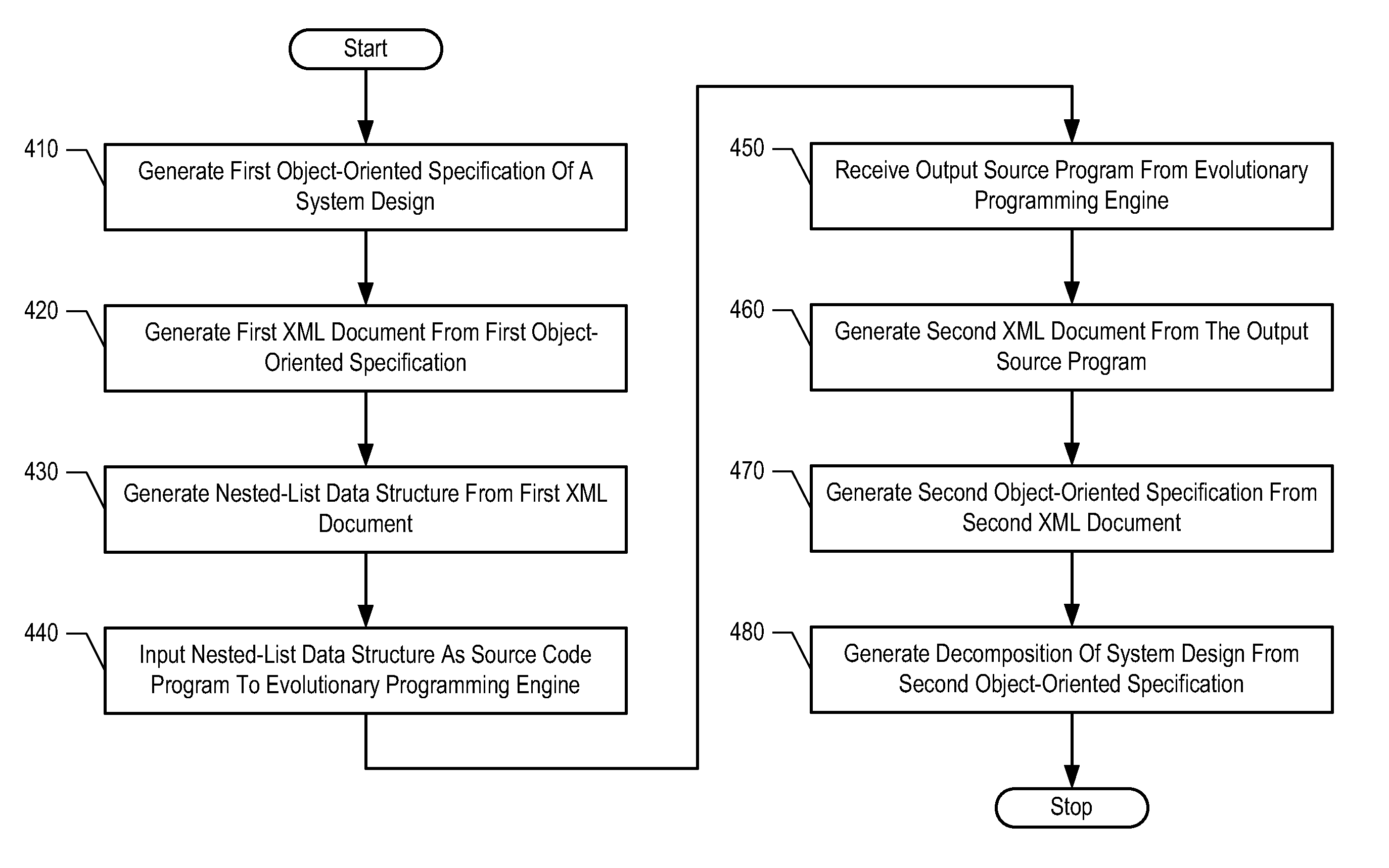
A technique for generating good system decompositions is disclosed. The illustrative embodiment uses evolutionary programming in combination with a fitness function to generate a system decomposition that has a low degree of coupling and a high degree of coherence. A system is represented by an object-oriented specification using the Unified Modeling Language (UML); the UML specification is then represented by an eXtended Markup Language (XML) document, and the contents of the document are transformed into a nested-list data structure that resembles source code in a functional programming language such as Common LISP. The nested-list data structure and an appropriate fitness function are input to an evolutionary programming engine that operates on the nested-list data structure as though it were a source code program, and generates an output source code program. A system decomposition is then derived from the output source code program.

Description

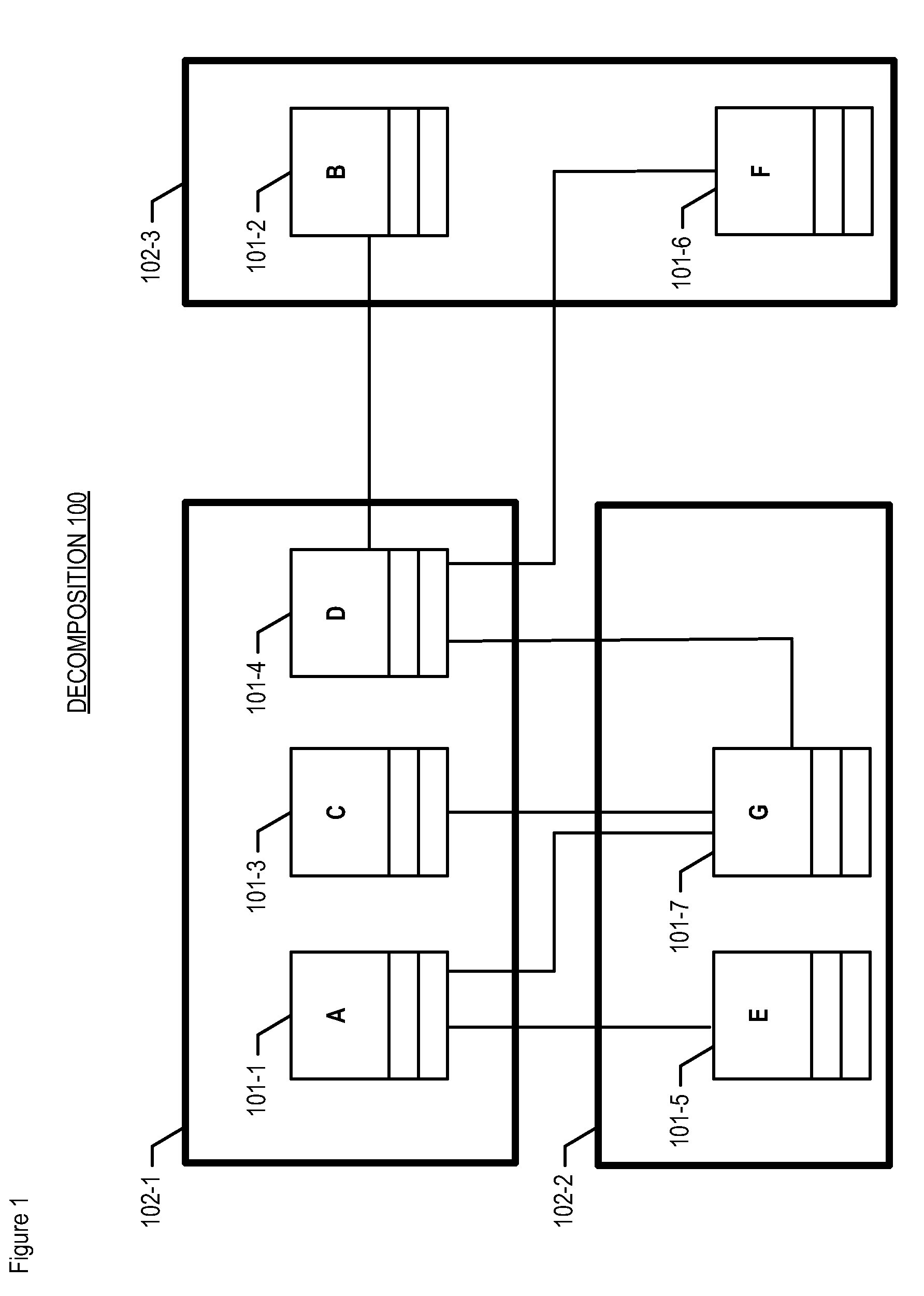
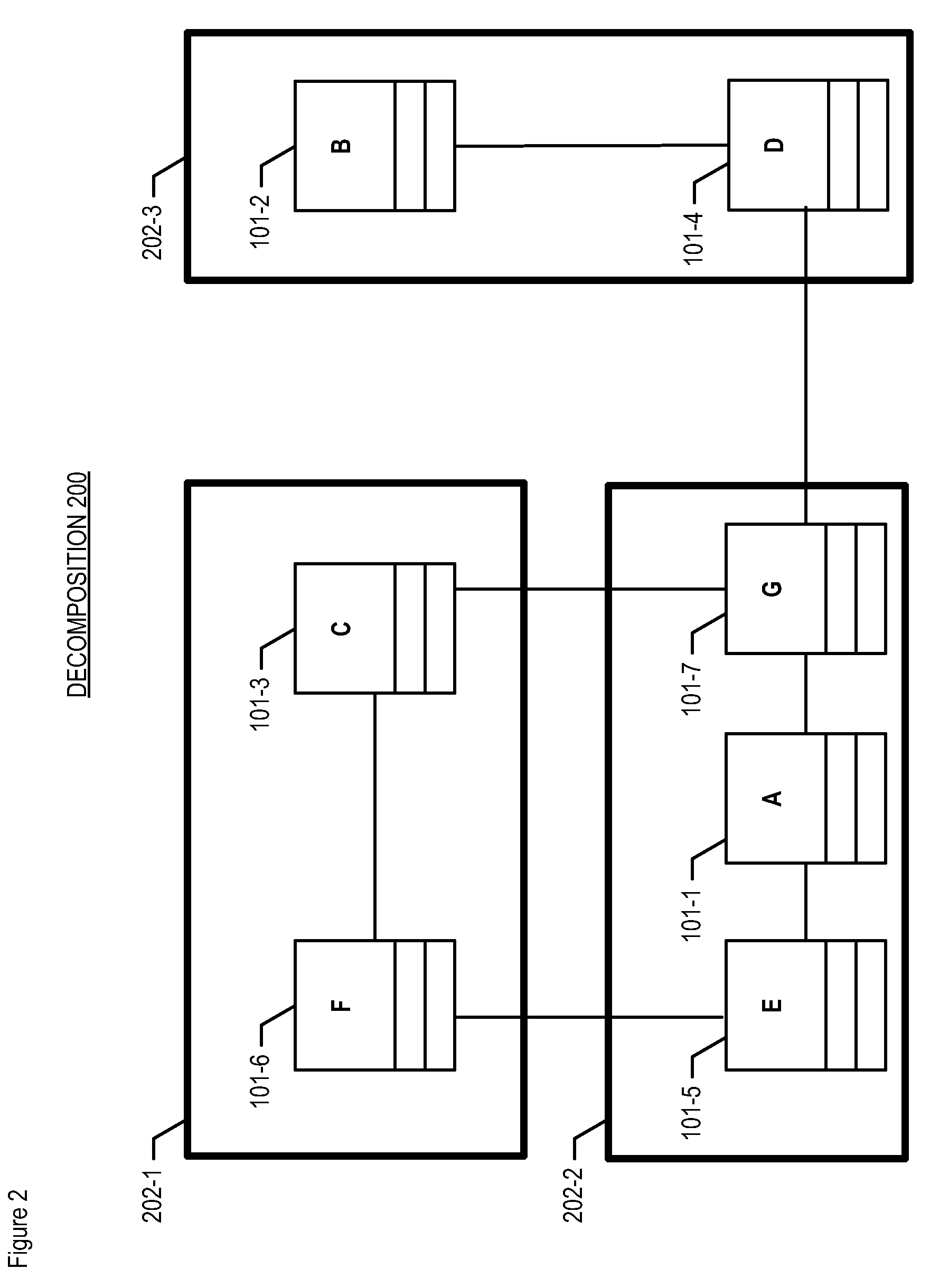
FIELD OF THE INVENTION[0001]The present invention relates to optimization in general, and, more particularly, to optimal system-subsystem decomposition.BACKGROUND OF THE INVENTION[0002]In some instances it is useful to decompose the elements of a system into a plurality of subsystems. Such decomposition can facilitate understanding of the system, implementation of the system (particularly when performed by a team of individuals), and visual presentation via a computer monitor or printed paper.[0003]FIG. 1 depicts first illustrative decomposition 100 of a system, in accordance with the prior art. As shown in FIG. 1, the system comprises six elements 101-1 through 101-6, interconnected as shown, and decomposition 100 comprises three subsystems: subsystem 102-1, comprising elements 101-1, 101-3, and 101-4; subsystem 102-2, comprising elements 101-5 and 101-7; and subsystem 102-3, comprising elements 101-2 and 101-6.[0004]FIG. 2 depicts second illustrative decomposition 200 of the same ...

Claims


Application Information

Patent Timeline
Patent Type & Authority Patents(United States)
IPC IPC(8): G06F9/44G06F17/30
CPCG06F8/10
Inventor MITCHELL, STEVEN W.
Owner LOCKHEED MARTIN CORP
Learn More