Open water recoverable drilling protector

a drilling protector and open water technology, applied in the direction of sealing/packing, mechanical equipment, borehole/well accessories, etc., can solve problems such as damage to the internal sealing surfa

Active Publication Date: 2012-12-04
VETCO GRAY
View PDF21 Cites 55 Cited by
  • Summary
  • Abstract
  • Description
  • Claims
  • Application Information

AI Technical Summary

Problems solved by technology

The production tree has internal sealing surfaces that could be damaged by the rotating drill pipe.

Method used


Image

  • Open water recoverable drilling protector
  • Open water recoverable drilling protector
  • Open water recoverable drilling protector

Examples


Embodiment Construction

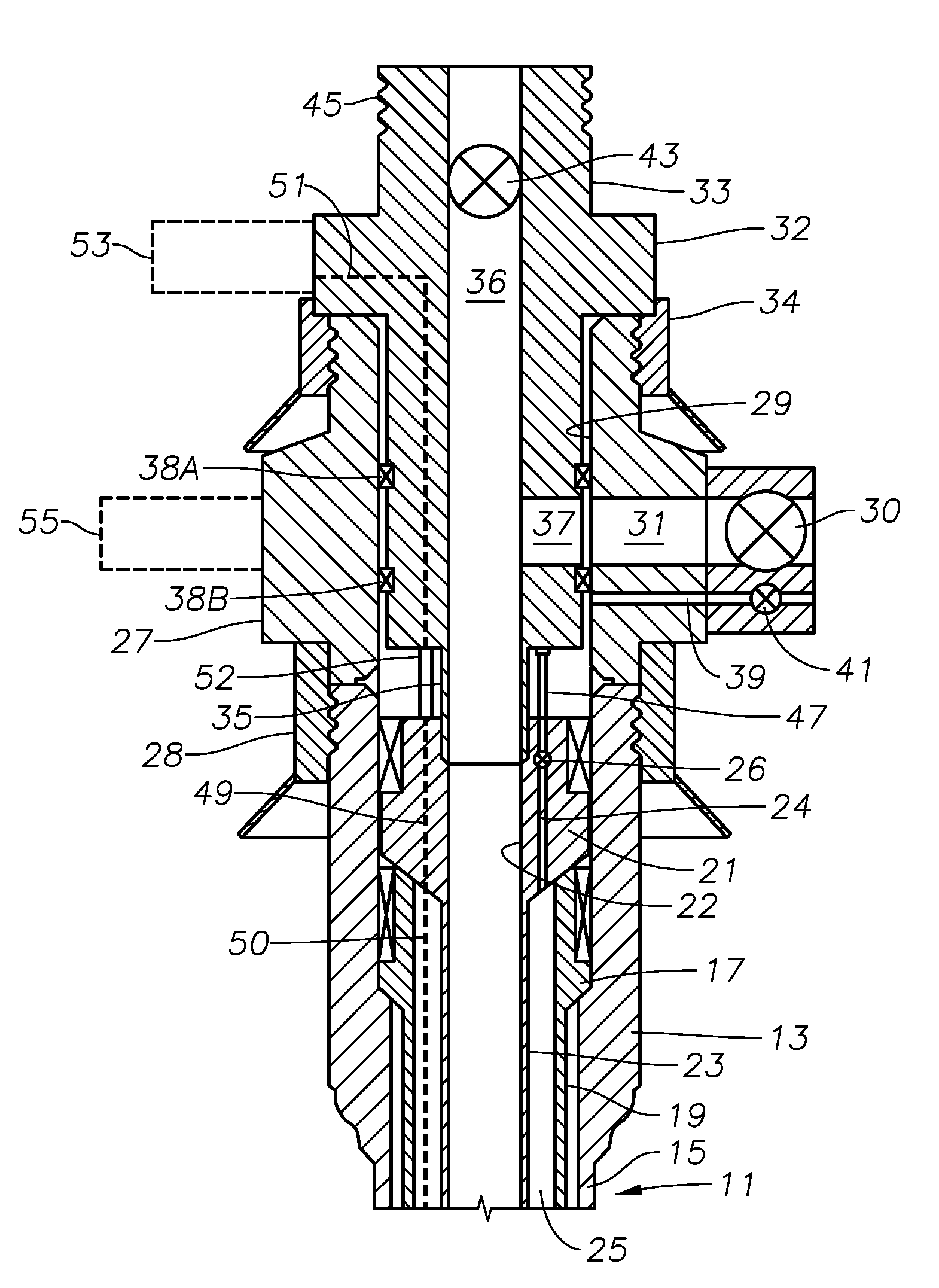
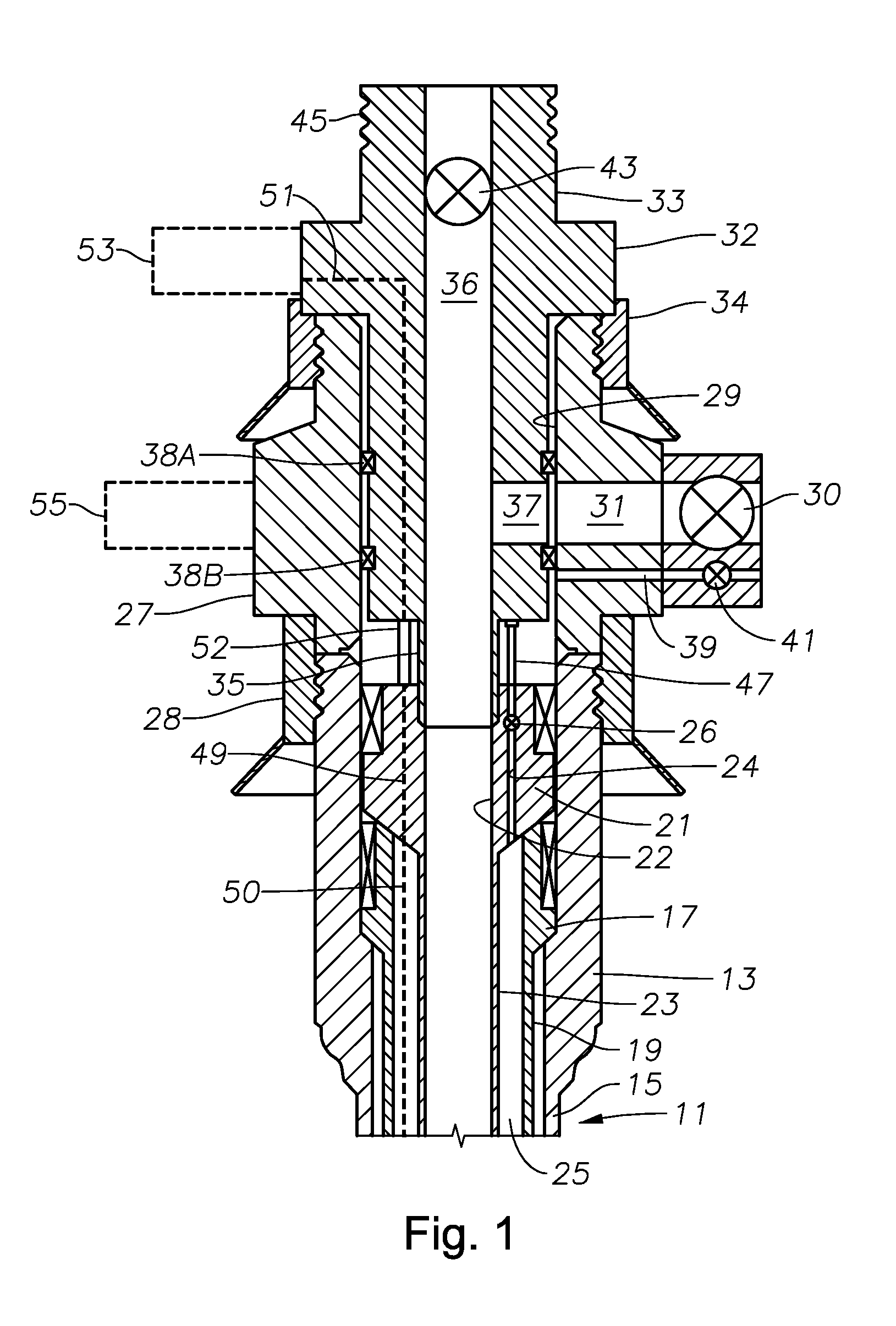
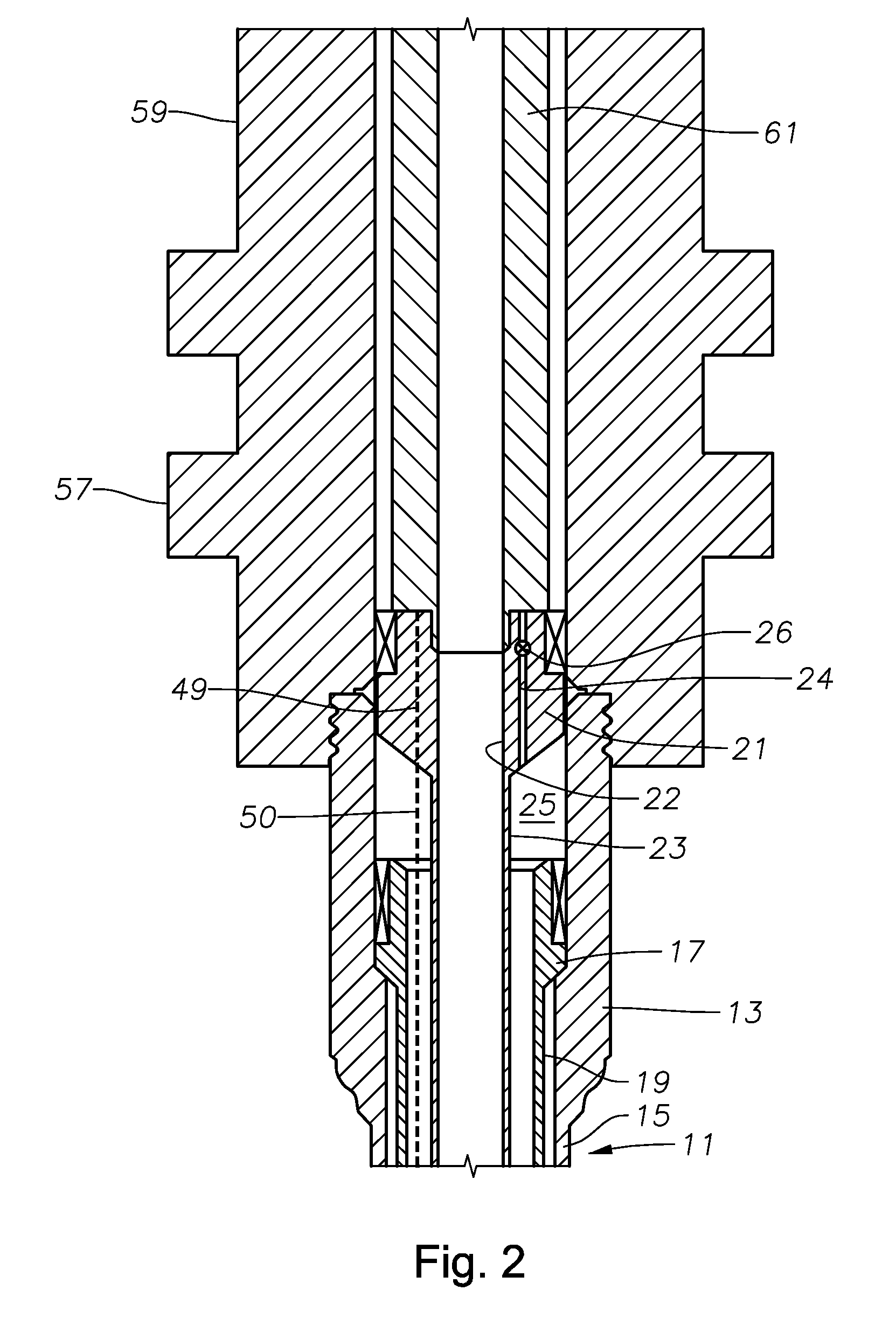
[0020]FIG. 1 shows in a side sectional view a wellhead housing 13 with a conductor casing 15 depending to a predetermined depth within a subsea well 11. A casing hanger 17 is landed within wellhead housing 13 with a string of casing 19 extending therefrom to another predetermined depth within subsea well 11. Also landed within wellhead housing 13 is a tubing hanger 21; a tubing string 23 is shown within the casing string 19 and supported on its upper end by the tubing hanger 21. In one example, the tubing string 23 extends to a production depth for receiving well fluid from within subsea well 11. Tubing hanger 21 has an axially extending production flow passage 22. A tubing annulus 25 is defined between the interior surface of string of casing 19 and the exterior surface of string of tubing 23. Tubing hanger 21 optionally may have a tubing annulus passage 24 extending axially through it offset from and parallel to production flow passage 22. In addition, a tubing annulus valve 26 ma...


PUM


Abstract

A method and system for retrieving a wear bushing from within a subsea wellhead assembly. The system includes a retrieval tool deployable on a wireline that inserts within the bushing. Latches on the tool radially project outwards and mate with a groove on the bushing inner surface. A hydraulically actuated jack is included with the tool and projects downward to the wellhead assembly to pull the bushing from its temporary coupling in the wellhead assembly. A remotely operated vehicle can be used to assist deploying the tool and for supplying hydraulics and / or control for operating the latch and the jack.

Description

CROSS REFERENCE TO RELATED APPLICATIONS[0001]This application claims priority to and the benefit of U.S. Provisional Application Ser. No. 61 / 079,636, filed Jul. 10, 2008, the full disclosure of which is hereby incorporated by reference herein.FIELD OF THE INVENTION[0002]This invention relates in general to production of oil and gas wells, and in particular to a wellhead assembly having a selectively removable wear bushing.DESCRIPTION OF RELATED ART[0003]Systems for producing oil and gas from subsea wellbores typically include a subsea wellhead assembly that includes a wellhead housing attached at a wellbore opening, where the wellbore extends through one or more hydrocarbon producing formations. Casing and tubing hangers are landed within the housing for supporting casing and production tubing inserted into the wellbore. The casing lines the wellbore, thereby isolating the wellbore from the surrounding formation. Tubing typically lies concentric within the casing and provides a cond...

Claims


Application Information

Patent Timeline
Patent Type & Authority Patents(United States)
IPC IPC(8): E21B23/00
CPCE21B17/1007E21B17/10E21B23/02E21B33/037
Inventor FENTON, STEPHEN P.
Owner VETCO GRAY
Why Eureka
Try Eureka