Natural forces power system

a power system and natural forces technology, applied in the direction of engines, mechanical equipment, machines/engines, etc., can solve the problems of significant change in water's specific gravity, and achieve the effect of increasing power production and producing power economically

Inactive Publication Date: 2006-07-13
BEHRENS CLIFFORD HIRAM
View PDF11 Cites 21 Cited by
  • Summary
  • Abstract
  • Description
  • Claims
  • Application Information

AI Technical Summary

Benefits of technology

[0003] This system produces power economically, in a simple and environmentally friendly manner. The following descriptions, based on a randomly chosen size should not be construed to be its limit in size. Rather, it should only be viewed as an exemplification of a single embodiment thereof. For example, more realistic sizes of the system's water tanks would be with capacities of several 100,000 gallons each, with commensurate larger components for greater power production. However, while capacities may vary, the sealed higher water tank 10 must retain its 12-foot interior height, and its bottom at the 31.95-foot mark for optimum performance at sea level sites. Therefore, tank size increases are to be made in the dimensions of width, length or both. With water tank capacity increases the open lower water tank 46 must retain its bottom height at 18 feet above the ground level, while conforming proportionately in capacity increases with the sealed higher water tank 10 at sea level locations. At appreciable higher elevations the tank heights must be lowered to equate with the locality's lowered atmospheric pressure.

Problems solved by technology

However, the addition of such could make a significant change from the water's specific gravity.

Method used


Image

  • Natural forces power system
  • Natural forces power system
  • Natural forces power system

Examples


Embodiment Construction

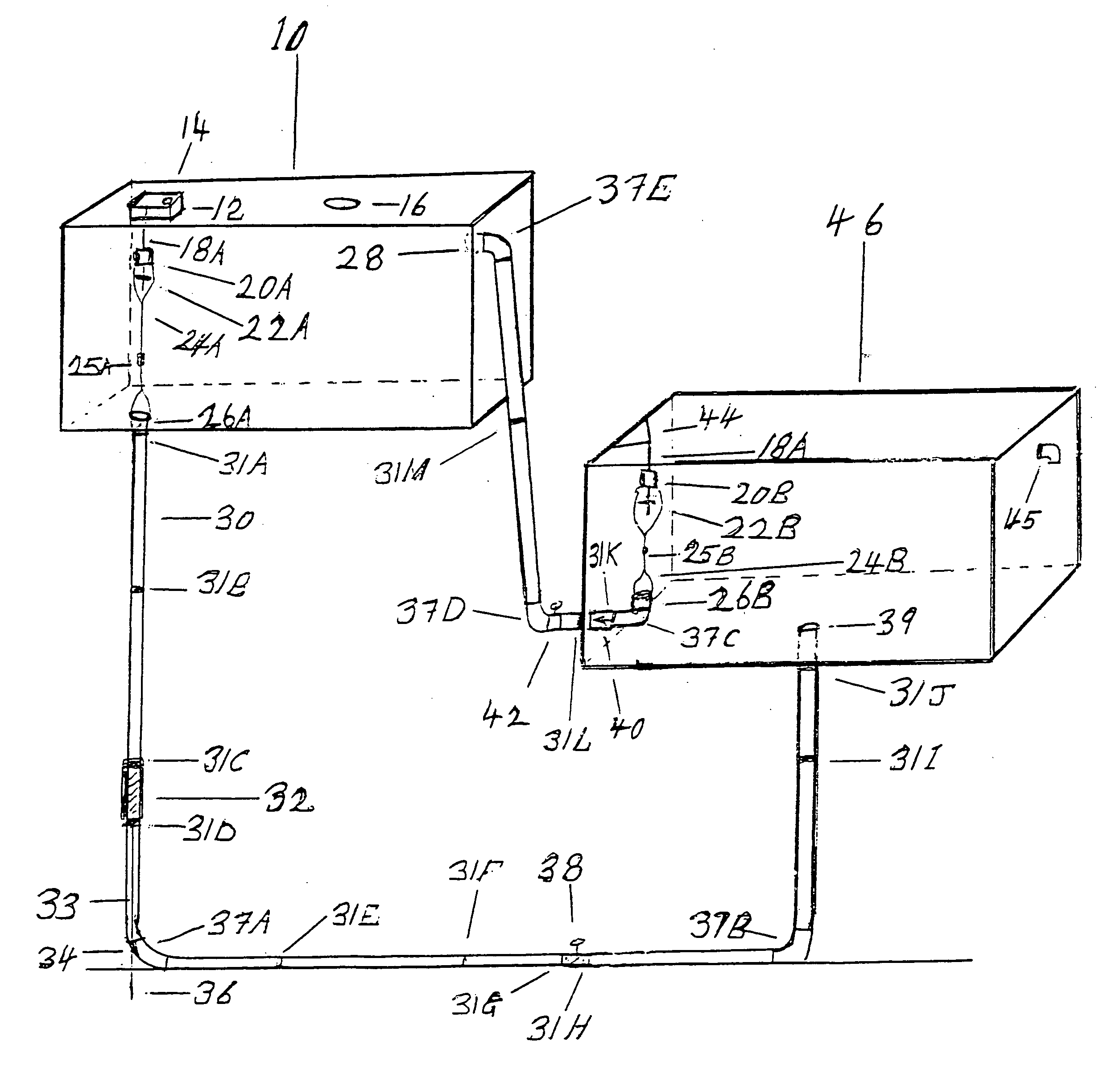
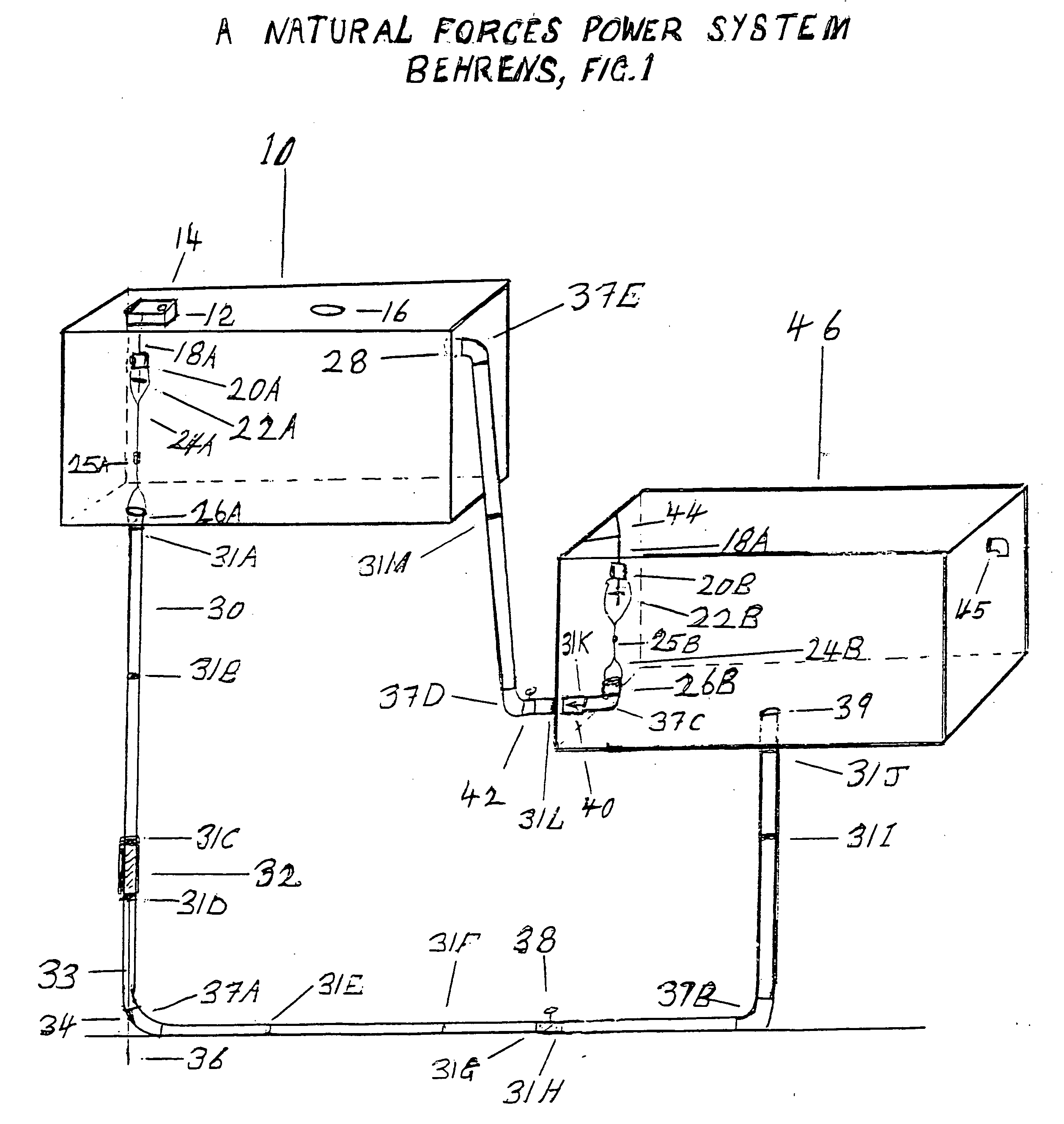
[0035] With tank 10's manhole cover secured, the system must first be filled with water. The initial filling procedures establish the residual two foot water level in tank 46 and purges out the air trapped between the water outlet valve 26B of tank 46 and the manual shut-off valve 42, which area encompasses the one-way check valve 40. Subsequent fillings for the purpose of topping off tank 10 need not be concerned with these one time initial requirements. The system is filled through its filler port 14. Please note that getting water up to the filler port is not within the scope of this invention and remains optional. First close the manual shut-off valves 38 and 42. Now fill tank 10 to overflowing. While tank 10 fills, the pipe leading from the manual shut-off valve 42 up into tank 10 also fills. Leave the filler port 14 open for one hour to dissipate any air, which may have entered the water through aeration. With the water still at the overflowing level gently screw in the filler...


PUM


Abstract

The two forces used are gravity and the atmospheric pressure. Gravity initiates the power phase by causing the water to fall from the elevated sealed water tank 10 to turn the turbine 32. The water lowers to 33.95 feet above ground level within the sealed water tank 10. A vacuum forms above the water. The water flows from the turbine into the elevated open water tank 46 to the level whereby its water outlet valve 26B opens. This affords a passage back into the elevated sealed water tank 10, through the check valve 40 and the manual shut-off valve 42. This initiates the recovery phase. The atmospheric pressure of 14.7 psi on the elevated open water tank 46 forces the water back into the sealed water tank 10 to relieve the vacuum. This pressure is capable to move the water up to 33.95 feet. Here it has only to move it up to 26.95 feet, realizing a 20.6 percent reserve force. With the water level again attaining maximum height in the sealed water tank 10, it is again released to repeat the cycle.

Description

BACKGROUND OF THE INVENTION [0001] This invention relates to the generation of electrical power. The idea of this invention occurred to me while taking a physics class. To the best of my knowledge, this system is without precedent. I have no related applications and I know of no similar prior art approaches. Currently energy is produced primarily with hydroelectric plants, coal and other carbon fuels, nuclear energy, windmills, and to a limited extent solar power and natural thermal sources. All of these have their disadvantages. These either depend on favorable weather or cause pollution or other environmental harm. Some are limited in scope or present a waste disposal problem. My invention has none of these disadvantages. It consists of a simple structure. Its operation is likewise simple. [0002] The forces used are gravity and the atmospheric pressure. A most positive aspect of this invention is that these forces are inexhaustible and do not diminish in force while used. While th...

Claims


Application Information

Patent Timeline
Patent Type & Authority Applications(United States)
IPC IPC(8): F03B17/02
CPCF03B17/005Y02E10/20
Inventor BEHRENS, CLIFFORD HIRAM
Owner BEHRENS CLIFFORD HIRAM
Why Eureka
Try Eureka