
Pitch bearing for wind turbine rotor blades

a technology of pitch bearing and wind turbine, which is applied in the direction of wind energy generation, liquid fuel engine components, non-positive displacement fluid engines, etc., can solve problems such as joint weakening

Active Publication Date: 2012-12-04
SIEMENS GAMESA RENEWABLE ENERGY AS
View PDF9 Cites 21 Cited by
  • Summary
  • Abstract
  • Description
  • Claims
  • Application Information

AI Technical Summary

Benefits of technology

[0017]An inventive wind turbine comprises a rotor with at least one inventive pitch bearing. The inventive wind turbine achieves the advantages discussed above with respect to the inventive pitch bearing.

Problems solved by technology

This may lead to loads acting on the joint between the reinforcement section and the bearing outer ring which could weaken the joint over time.

Method used


Image

  • Pitch bearing for wind turbine rotor blades
  • Pitch bearing for wind turbine rotor blades
  • Pitch bearing for wind turbine rotor blades

Examples


Embodiment Construction

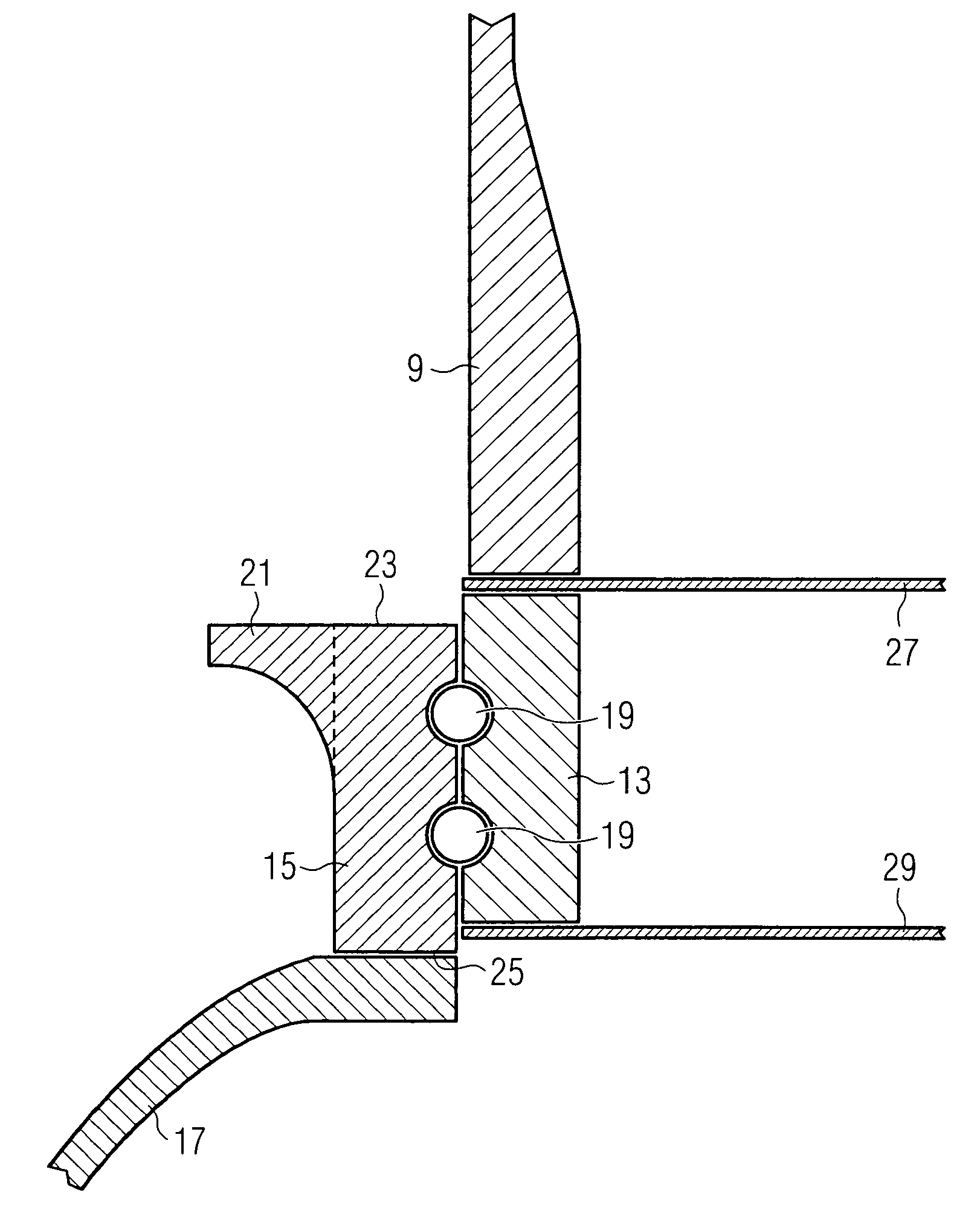
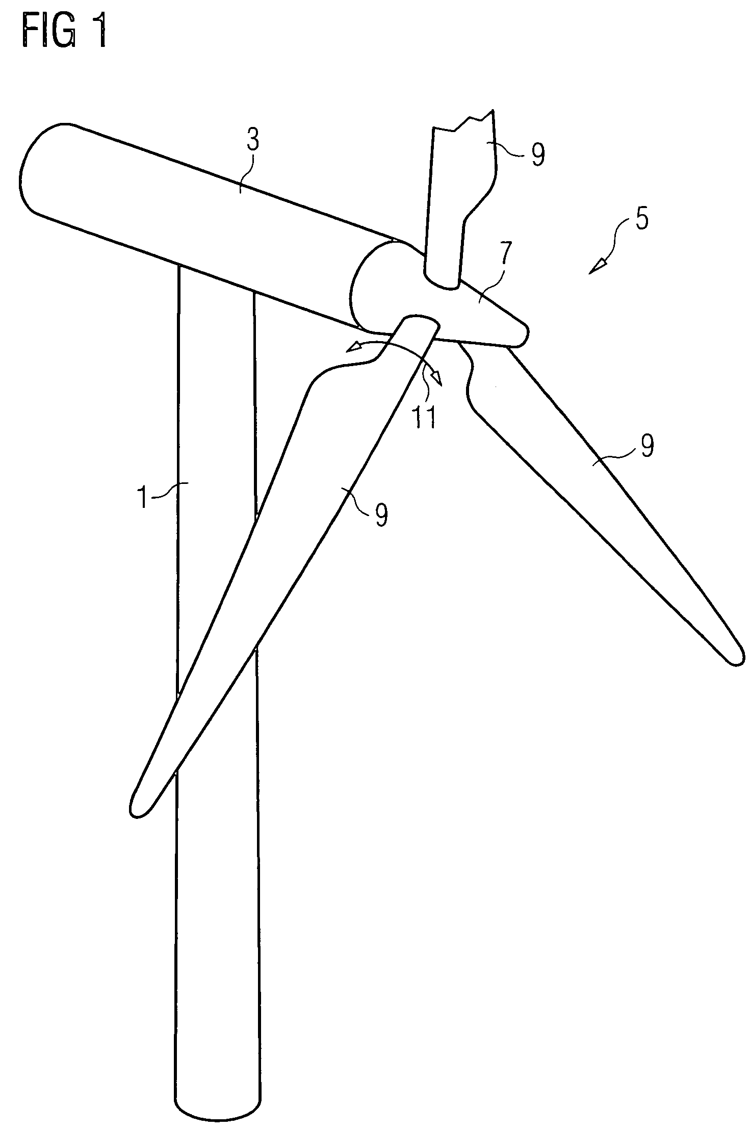
[0024]A wind turbine with an inventive pitch bearing is shown in FIG. 1. The wind turbine comprises a tower 1, a nacelle 3 which is mounted pivotably about the tower axis at the tower top and which houses the generator of the wind turbine, and a rotor 5 which is rotatably connected to the generator inside the nacelle. The rotor 5 comprises a rotor hub 7 and, in the pre-sent embodiment, three rotor blades 9 which are mounted to the rotor hub so as to be rotatable about a pitch axis, as indicated for one of the blades 9 by the arrow 11.

[0025]Although the wind turbine shown in FIG. 1 is equipped with three rotor blades, the rotor may have a different number of blades, for example only two blades. In general, any number of blades would be possible, although two-bladed rotors and, in particular, three-bladed rotors are the most common.

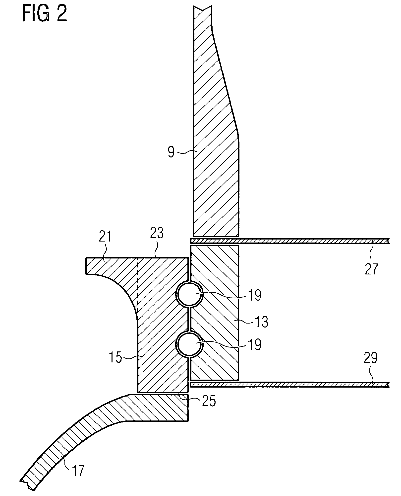
[0026]The wind turbine rotor blades 9 are mounted to the rotor hub 7 by use of pitch bearings. A first embodiment of a pitch bearing usable in the wind tur...


PUM


Abstract

A pitch bearing for a wind turbine rotor comprises a rotor hub and at least one rotor blade, the pitch bearing comprising a cylindrical inner bearing ring connectable to a rotor blade of the wind turbine rotor, a cylindrical outer bearing ring connectable to the rotor hub of the wind turbine rotor and an annular reinforcement section for reinforcing the outer bearing ring. The annular reinforcement section adjoins the cylindrical outer bearing ring at its radial outer surface.

Description

CROSS REFERENCE TO RELATED APPLICATIONS[0001]This application claims the benefits of U.S. Provisional application No. 60 / 976,560 filed Oct. 1, 2007 and is incorporated by reference herein in is entirety.FIELD OF INVENTION[0002]The present invention relates to a pitch bearing for wind turbine rotor blades with an inner bearing ring connectable to a rotor blade of a wind turbine rotor and an outer bearing ring connectable to a rotor hub of a wind turbine rotor. In addition, the invention relates to a wind turbine with at least one such pitch bearing.BACKGROUND OF THE INVENTION[0003]In modern wind turbines the rotor blades are mounted to the hub via pitch bearings which allow for controlling the loads acting on the blades by changing the pitch of the blades relative to the wind. Those bearings usually comprise a cylindrical inner bearing ring to which the rotor blade is fixed and a cylindrical outer bearing ring which is fixed to the rotor hub. Between both bearing rings one or more ro...

Claims


Application Information

Patent Timeline
Patent Type & Authority Patents(United States)
IPC IPC(8): F16C33/00F03D11/00
CPCF03D7/0224F03D11/0008F16C19/18F16C33/58F16C33/60F05B2260/301F16C2226/60F16C2300/14Y02E10/721Y02E10/722Y02E10/723F16C2360/31F05B2260/79F03D80/70Y02E10/72
Inventor LARSEN, MARTIN HEDEGAARDNIELSEN, ANDERS VANGSGAARDPOULSEN, STEFFEN FRYDENDAL
Owner SIEMENS GAMESA RENEWABLE ENERGY AS
Learn More