
Parallel image encoding

a parallel image and encoding technology, applied in the field of encoding image data, can solve the problems of significant demands on the system in terms of buffer capacity and memory bandwidth, and cannot be easily adapted to such parallelization, and achieve the effect of large storage capacity and high memory bandwidth capacity

Active Publication Date: 2012-12-11
ARM LTD
View PDF6 Cites 1 Cited by
  • Summary
  • Abstract
  • Description
  • Claims
  • Application Information

AI Technical Summary

Benefits of technology

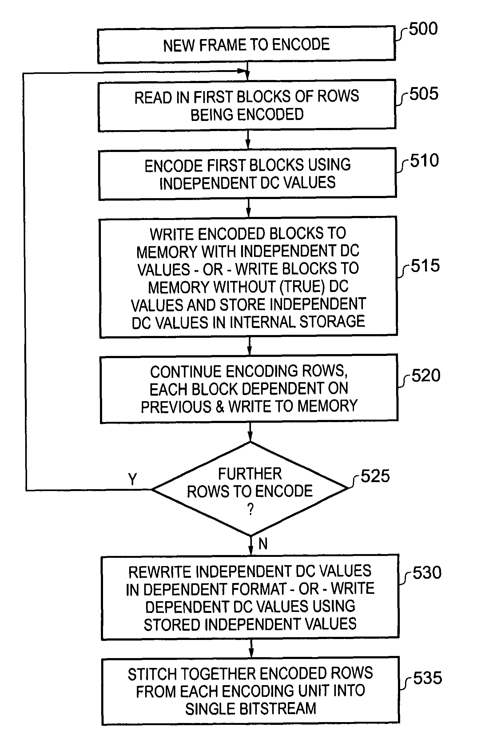
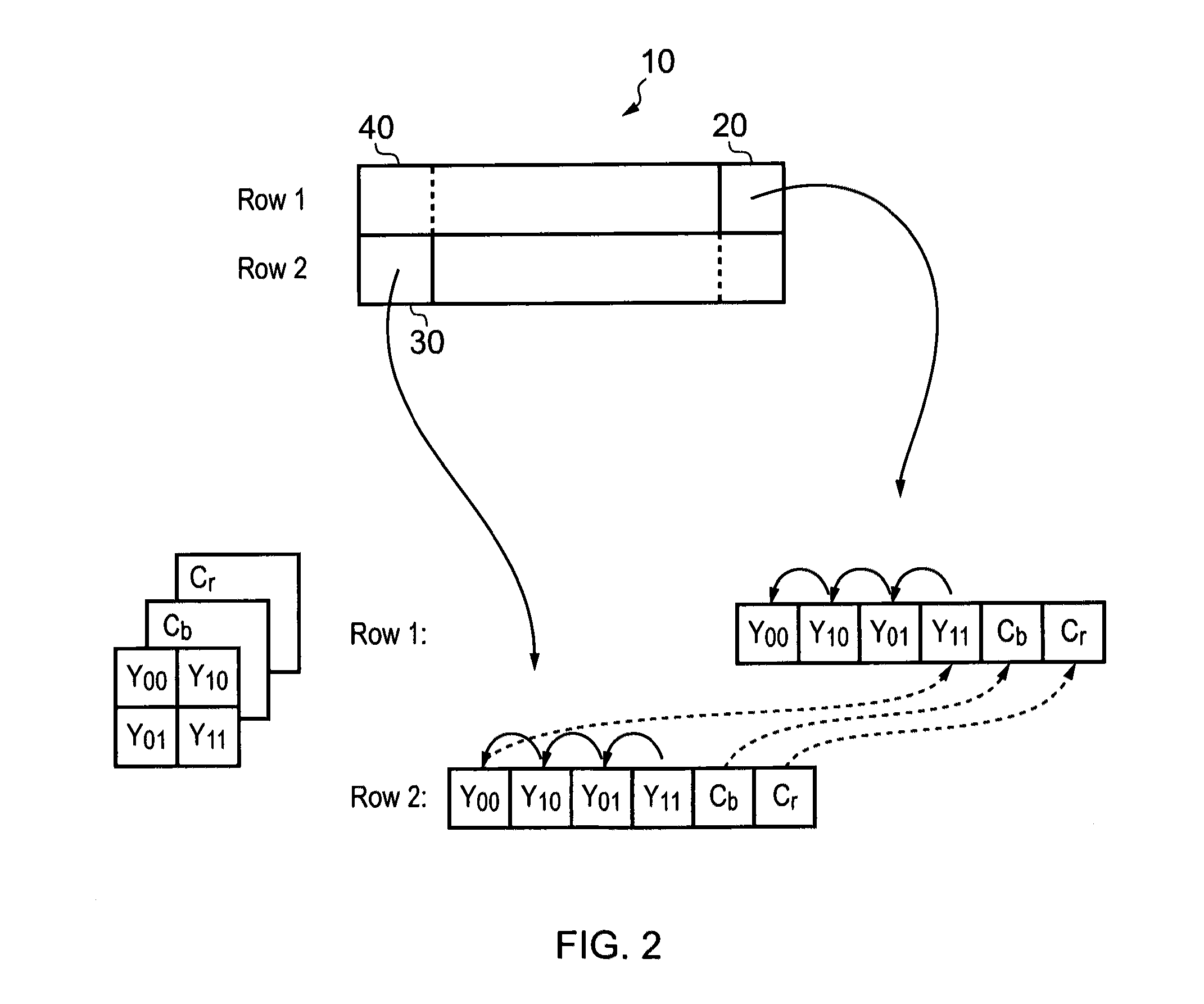
The present invention provides an image encoding apparatus that can efficiently encode image data into a predetermined format. The apparatus includes a first encoding unit and a second encoding unit that perform the encoding process in parallel, allowing for the simultaneous encoding of multiple blocks of pixels. The encoding process is performed by performing a characteristic encoding value determination operation on a last block of pixels in a preceding group, followed by the determination of a dependent characteristic encoding value for the first block of the second group. This allows for the parallelization of the encoding process and reduces the amount of intermediate format data that needs to be processed, resulting in improved efficiency.

Problems solved by technology

However, the process of encoding image encoding formats such as JPEG, in which many blocks of image data within a given picture are encoded with respect to the block of image data which precedes them, is not easily adapted to such parallelization, since the encoding is by its nature sequential, each block in a chain of blocks requiring the previous block to be encoded in order to be encoded itself in dependence thereon.
However, on the one hand this approach suffers from the disadvantage that a large quantity of intermediate data is generated by the first parallelized steps, which places significant demands on the system in terms of buffer capacity and memory bandwidth.
Such demands are particularly undesirable in the context of systems with limited resources.
On the other hand the technique described also suffers from inherent image degradation as can be seen in FIGS. 6 and 7 therein.

Method used


Image

  • Parallel image encoding
  • Parallel image encoding
  • Parallel image encoding

Examples


Embodiment Construction

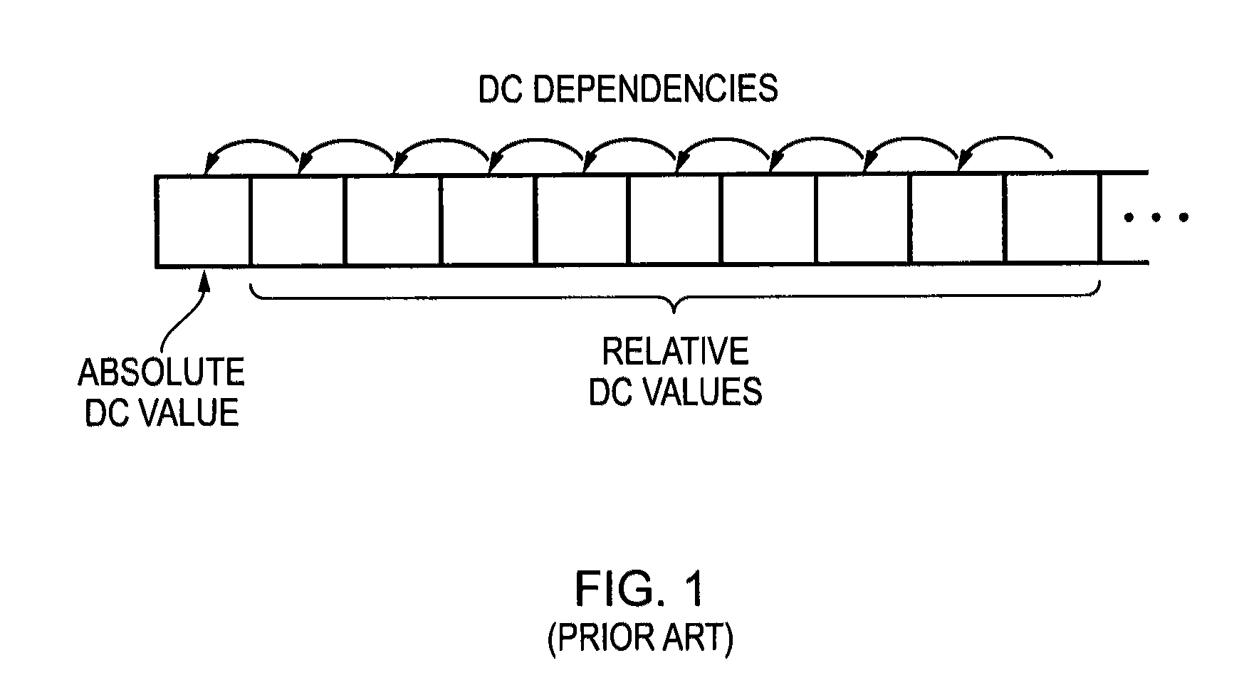
[0053]FIG. 1 schematically illustrates a sequence of encoded blocks of pixels in a predetermined image encoding format such as one of the JPEG formats. The first block of pixels in the sequence is independently encoded and its characteristic encoding value (DC) is encoded in absolute terms. The following blocks of pixels however are each encoded with reference to the preceding block of pixels, wherein the characteristic encoding value for each block of pixels is dependently encoded, each characteristic encoding value (DC value) being encoded as a relative value referring to the previous characteristic encoding value. An entire frame of image data can be encoded as such a sequence, with the sequence of blocks following the familiar raster scan pattern through the frame. The sequential nature of the DC dependencies schematically illustrated in FIG. 1 demonstrates a difficulty for the parallelization of the encoding task, because in order to encode any given dependently encoded block o...


PUM


Abstract

An image encoding apparatus is configured to encode image data comprising a sequence of unencoded blocks of pixels into a sequence of encoded blocks of pixels in a predetermined image encoding format. Each encoded block of pixels has a characteristic encoding value representative of its corresponding unencoded block of pixels, and a plurality of dependently encoded blocks of pixels each have a dependent characteristic encoding value which is defined with reference to the characteristic encoding value for a preceding encoded block of pixels. The image encoding apparatus comprises a first encoding unit configured to perform an encoding process on a first group of the unencoded blocks of pixels and a second encoding unit configured to perform the encoding process on a second group of the unencoded blocks of pixels, wherein the encoding process generates an encoded block of pixels in the predetermined image encoding format, and wherein the second group immediately follows the first group and a first block of the second group is comprised in the plurality of dependently encoded blocks of pixels. The first encoding unit and the second encoding unit are configured to perform the encoding process in parallel on respective unencoded blocks of pixels in the first group and in the second group on a block-by-block basis. The image encoding apparatus is configured to perform a characteristic encoding value determination operation to determine the characteristic encoding value for a last block of pixels in the first group, before determining the dependent characteristic encoding value for the first block of the second group.

Description

BACKGROUND OF THE INVENTION[0001]1. Field of the Invention[0002]The present invention relates to encoding image data according to a predetermined image encoding format. More particularly, this invention relates to image encoding apparatuses comprising more than one encoding unit, wherein the encoding units are configured to perform the encoding process in parallel.[0003]2. Description of the Prior Art[0004]It is known to provide an image encoding apparatus configured to encode image data according to a predetermined image encoding format. For example, it is known to provide an encoding apparatus which is configured to receive image data in a raw format (e.g. RGB or YUV) and to encode the image data according to a predetermined image encoding format such as those formats defined by the Joint Photographic Experts Group, commonly referred to generically as the JPEG format.[0005]Image encoding formats such as JPEG can enable a significant reduction in the file size of image data without...

Claims


Application Information

Patent Timeline
Patent Type & Authority Patents(United States)
IPC IPC(8): G06K9/36G06K9/46
CPCH04N19/60H04N19/593H04N19/85H04N19/18H04N19/436H04N19/176H04N19/156H04N19/127
Inventor MALMBORG, LARS INGVARDOFFINGER, REIMAR GISBERT
Owner ARM LTD
Learn More