Coordinate measuring machine

a technology of coordinate measuring machine and measuring value, which is applied in the direction of speed measurement using gyroscopic effects, instruments, and using wave/particle radiation means. it can solve the problems of error in the measurement value of the coordinate measuring machine and the inability to correct the error in the measurement valu

Active Publication Date: 2012-12-11
MITUTOYO CORP
View PDF11 Cites 11 Cited by
  • Summary
  • Abstract
  • Description
  • Claims
  • Application Information

AI Technical Summary

Benefits of technology

[0011]An object of the invention is to provide a coordinate measuring machine that is capable of properly correcting an error in a measurement value even when probes of different lengths are used or when an attitude of a probe is changed.
[0017]According to the above arrangement, the coordinate measuring machine is capable of properly correcting an error in a measurement value even when probes of different length are used or when the attitude of the probe is changed. Incidentally, the acceleration of the scanning movement of the probe may be calculated based on a scanning vector as in the surface profile measuring instrument disclosed in the Document 1, or, alternatively, may be measured using an acceleration sensor, position sensor and the like.
[0020]According to the above arrangement, since the coordinate measuring machine includes the phase-difference correction-amount calculating unit for calculating the phase-difference correction-amount for correcting the phase difference between the respective movement axes, the phase difference between the respective movement axes can be properly corrected, thus further properly correcting the error in the measurement value.
[0026]Since the correction-amount calculating unit of the above arrangement calculates the correction amount based on the displacement of the moving mechanism obtained by the displacement acquiring unit, the coordinate measuring machine can properly correct the error in the measurement value.

Problems solved by technology

However, since the moving mechanism is deformed on account of acceleration caused during the scanning movement of the probe, an error occurs between the obtained displacement of the moving mechanism and the position of the measurement piece, resulting in an error in the measurement value of the coordinate measuring machine.
Accordingly, the surface profile measuring instrument disclosed in the Document 1 fails to calculate an appropriate correction amount in the above circumstances, thus unable to properly correct an error in the measurement value.

Method used


Image

  • Coordinate measuring machine
  • Coordinate measuring machine
  • Coordinate measuring machine

Examples


first embodiment

[0048]A first exemplary embodiment of the invention will be described below with reference to the drawings.

Overall Arrangement of Coordinate Measuring Machine

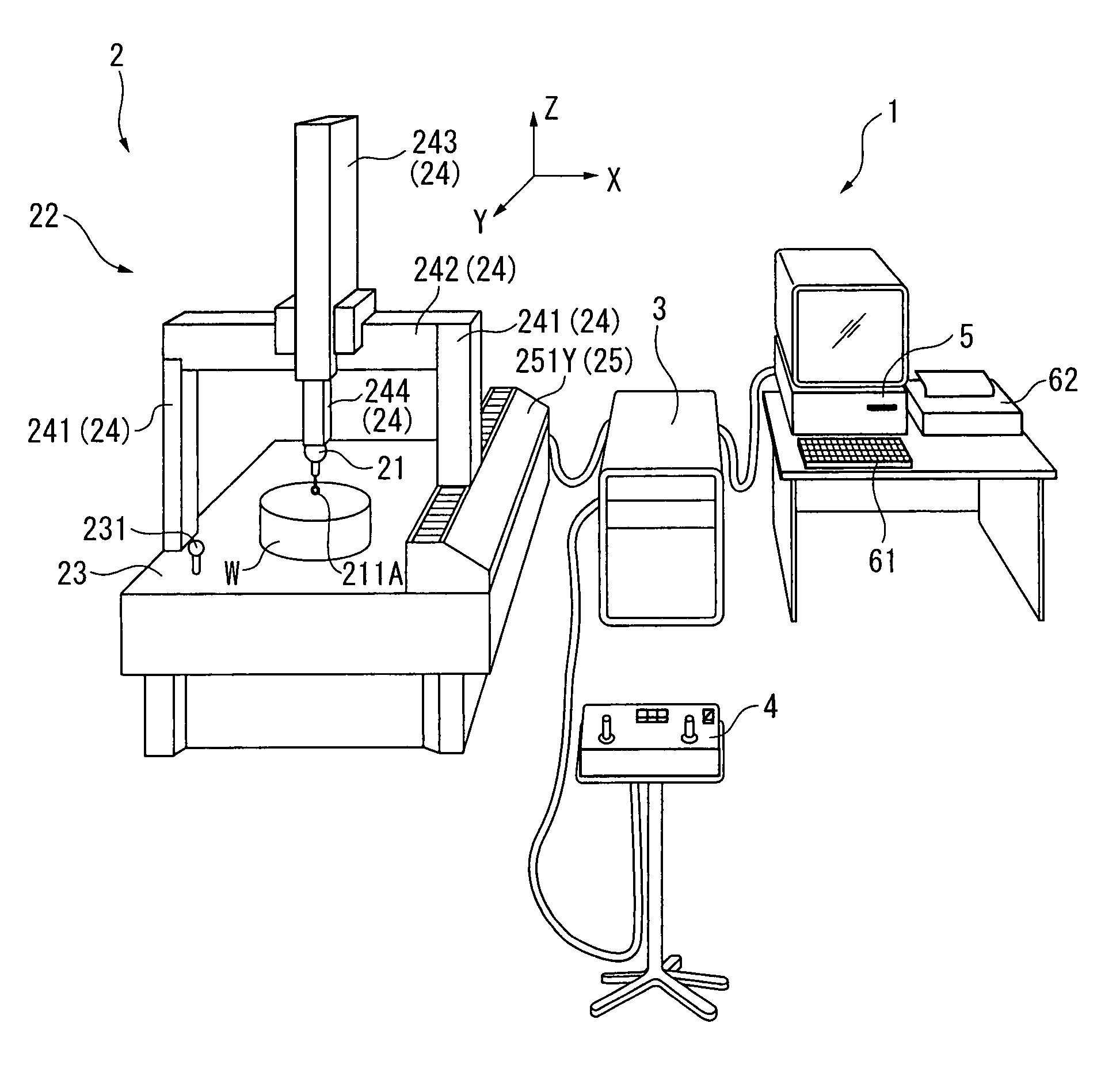
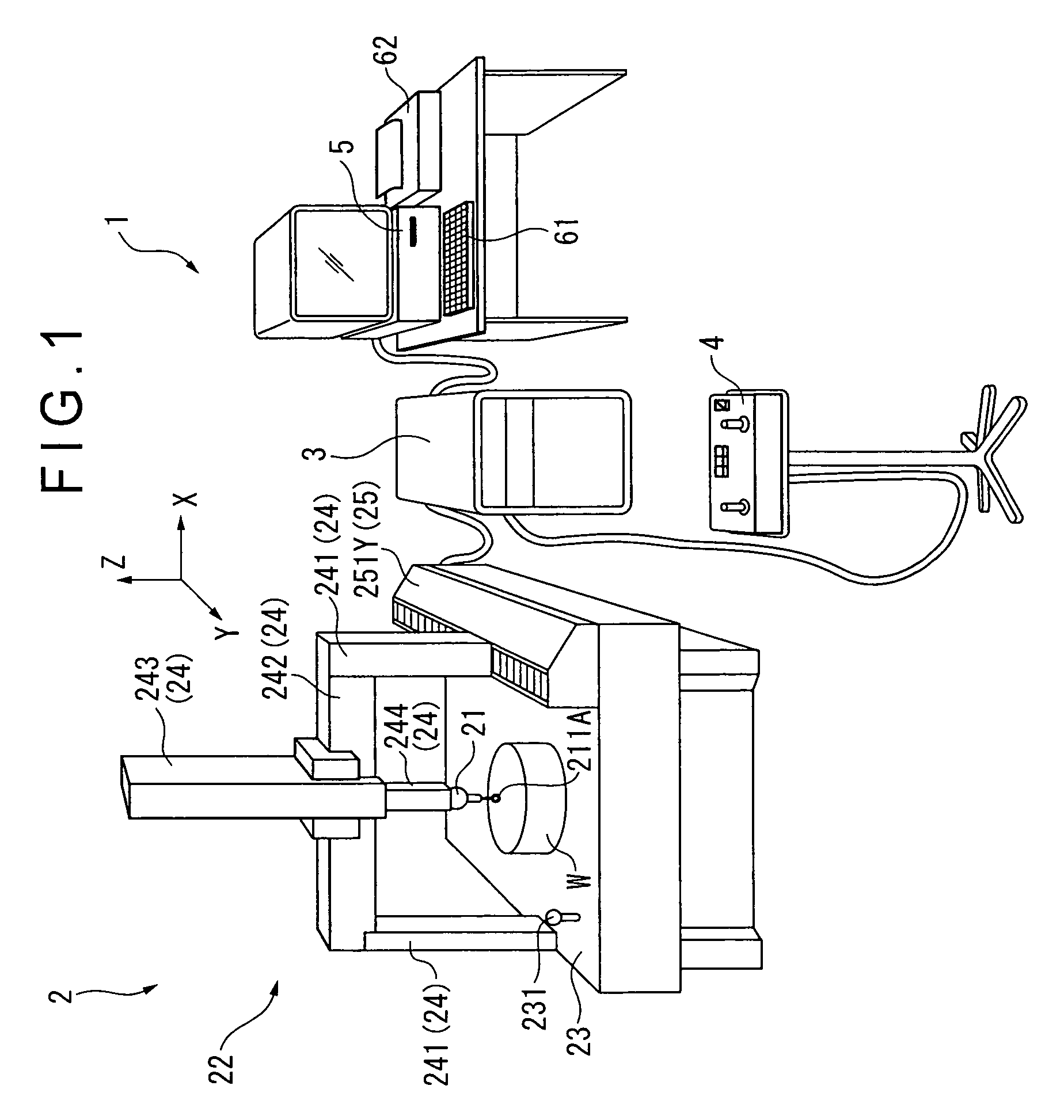
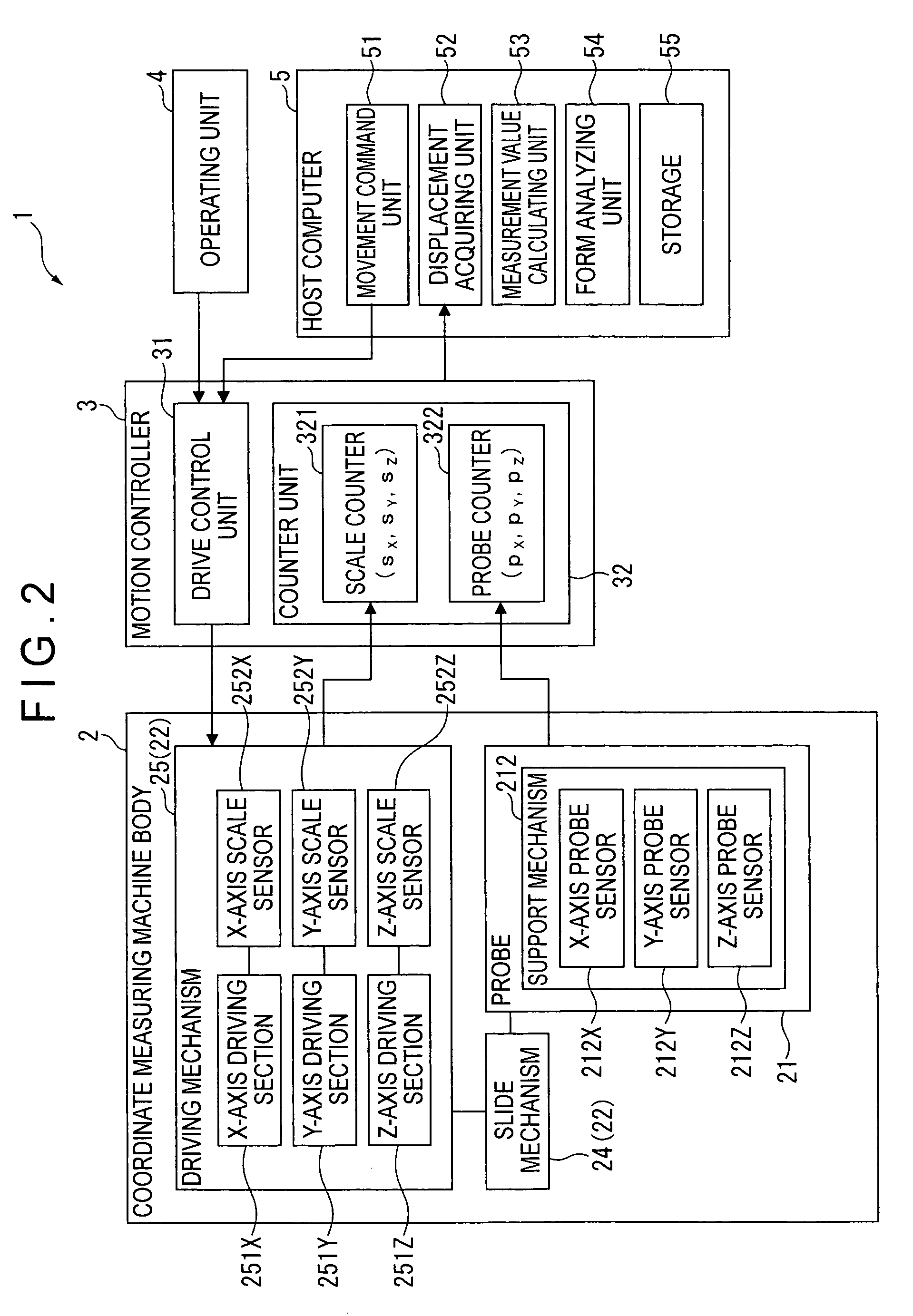
[0049]FIG. 1 is a schematic illustration showing an entire coordinate measuring machine according to the first exemplary embodiment of the invention. FIG. 2 is a block diagram showing an overall arrangement of a coordinate measuring machine 1. Incidentally, an upward direction is defined as +Z-axis direction and two axes orthogonal to the Z-axis are respectively defined as X-axis and Y-axis in FIG. 1, which is the same in the subsequent drawings.

[0050]As shown in FIG. 1, the coordinate measuring machine 1 includes: a coordinate measuring machine body 2; a motion controller 3 for controlling the drive of the coordinate measuring machine body 2; an operating unit 4 that applies a command to the motion controller 3 through an operation lever and the like to manually operate the coordinate measuring machine body 2; a host computer ...

second embodiment

[0134]A second exemplary embodiment of the invention will be described below with reference to the attached drawings.

[0135]Incidentally, the same reference numeral will be attached to those components having been described and the description thereof will be omitted.

[0136]FIG. 13 is a block diagram showing an overall arrangement of a coordinate measuring machine 1A according to the second exemplary embodiment of the invention.

[0137]In the first exemplary embodiment, the movement-estimating unit 7 includes the acceleration-estimating unit 71 to calculate the acceleration A of the scanning movement of the probe 21. In contrast, in this exemplary embodiment, a movement-estimating unit 7A includes, as well as the acceleration-estimating unit 71, a frequency-estimating unit 72 that estimates a frequency of the scanning movement of the probe 21.

[0138]Further, in the first exemplary embodiment, the correction-amount calculating unit 8 includes the acceleration correction-amount calculating...


PUM


Abstract

A coordinate measuring machine includes: a probe provided with a measurement piece; a moving mechanism that effects a scanning movement of the probe; and a host computer for controlling the moving mechanism. The host computer includes a displacement acquiring unit for acquiring a displacement of the moving mechanism and a measurement value calculating unit for calculating a measurement value. The measurement value calculating unit includes a correction-amount calculating unit for calculating a correction amount for correcting a position error of the measurement piece and a correcting unit for correcting the position error of the measurement piece based on the displacement of the moving mechanism and the correction amount. The correction-amount calculating unit calculates a translation-correction amount for correcting a translation error of the probe at a reference point on the probe and a rotation-correction amount for correcting a rotation error of the probe according to a rotation angle of the probe around the reference point and a length of the probe from the reference point to the measurement piece.

Description

BACKGROUND OF THE INVENTION[0001]1. Field of the Invention[0002]The present invention relates to a coordinate measuring machine.[0003]2. Description of Related Art[0004]A coordinate measuring machine typically includes a probe having a measurement piece that is moved along a surface of an object to be measured, a moving mechanism that holds and moves the probe while scanning the surface and a controller for controlling the moving mechanism (see, for instance, Document 1: JP-A-2008-89578).[0005]In such a coordinate measuring machine, a displacement of the moving mechanism is obtained to detect the position of the measurement piece, based on which a surface profile of the object and the like is measured.[0006]However, since the moving mechanism is deformed on account of acceleration caused during the scanning movement of the probe, an error occurs between the obtained displacement of the moving mechanism and the position of the measurement piece, resulting in an error in the measureme...

Claims


Application Information

Patent Timeline
Patent Type & Authority Patents(United States)
IPC IPC(8): G01C17/38G01P21/00
CPCG01B21/045
Inventor ISHIKAWA, NOBUHIRO
Owner MITUTOYO CORP
Why Eureka
Try Eureka