Method for identifying redundant signal paths for self-gating signals

a signal path and signal path technology, applied in the field of signal path optimization, can solve the problems of difficult to meet the timing requirements of a particular circuit, signals may inadvertently be redundant in a design, and the type of redundant path is not easily detectable by conventional design tools

Inactive Publication Date: 2012-12-11
APPLE INC
View PDF7 Cites 2 Cited by
  • Summary
  • Abstract
  • Description
  • Claims
  • Application Information

AI Technical Summary

Problems solved by technology

Depending on how large the fan-out, it may be difficult to meet the timing requirements of the particular circuit.
More particularly, some signals may inadvertently be redundant in a design.
This type of redundant path is not easily detectable by conventional design tools.
These redundant signals can be problematic particularly when the have a large fanout.

Method used


Image

  • Method for identifying redundant signal paths for self-gating signals
  • Method for identifying redundant signal paths for self-gating signals
  • Method for identifying redundant signal paths for self-gating signals

Examples


Embodiment Construction

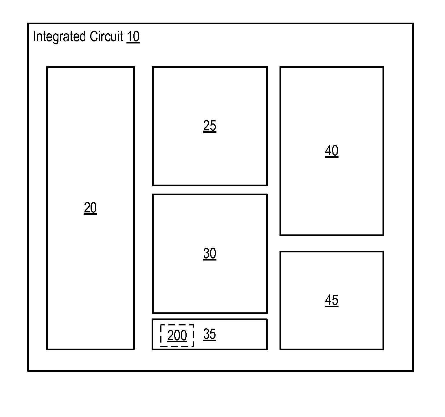
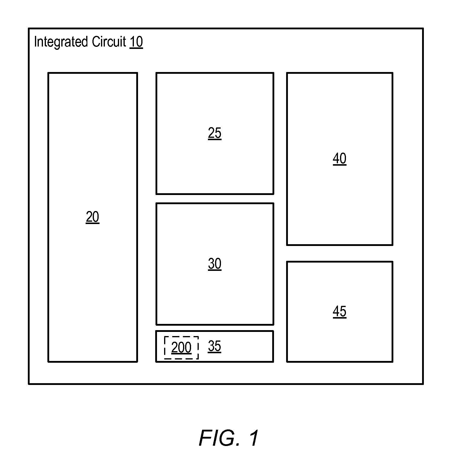
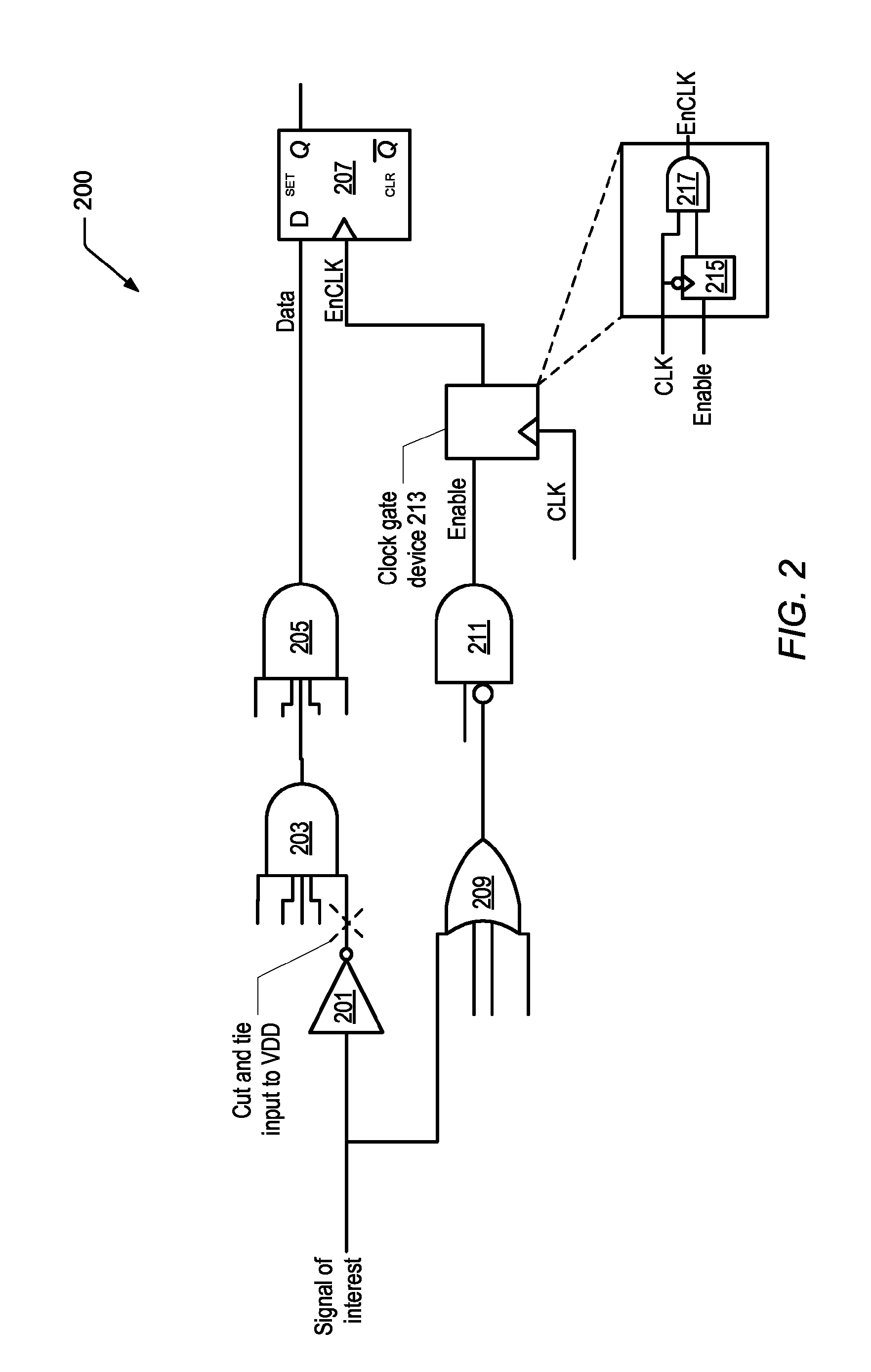
[0007]Various embodiments of a method for identifying redundant signal paths for self-gating signals are disclosed. Broadly speaking, a method is contemplated in which redundant signal paths may be identified and removed. More particularly, certain redundant paths such as those created by a signal that feeds both an input to a cone of logic of a data input to a clocked state element such as a flip-flop, and a clock gate circuit that is used to gate the same flip-flop may be problematic and therefore identified and removed.

[0008]In one embodiment, the method includes determining whether a given input to a logic circuit is coupled to both an input of a cone of logic that is coupled to a data input of a clocked state element and a clock gate circuit that is coupled to disable a clock input to the clocked state element. In addition, the method may include removing the given input from the cone of logic such that the given input is no longer coupled to the input of the cone of logic in r...


PUM


Abstract

A method for identifying and removing redundant signal paths includes determining whether a given input to a logic circuit is coupled to both an input of a cone of logic of a data input of a clocked state element and a clock gate circuit that is coupled to disable a clock input to the clocked state element. The method may include removing the given input from the cone of logic such that the given input is no longer coupled to the input of the cone of logic responsive to determining that the given input is coupled to both the input of the cone of logic and the clock gate circuit. The method may include preserving the given input to the clock gate circuit such that the given input continues to be coupled to the clock gate circuit after being removed from the input of the cone of logic.

Description

[0001]This patent application claims priority to Provisional Patent Application Ser. No. 61 / 423,240, filed Dec. 15, 2010, the content of which is herein incorporated by reference in its entirety.BACKGROUND[0002]1. Technical Field[0003]This disclosure relates to integrated circuit design, and more particularly to signal path optimization.[0004]2. Description of the Related Art[0005]Signal paths on integrated circuits can in many cases be routed through various cones of logic. In addition, various ones of these signals may have a large fan-in or a large fanout. Depending on how large the fan-out, it may be difficult to meet the timing requirements of the particular circuit. This may be particularly true for signals that are common to many parts of the integrated circuit.[0006]More particularly, some signals may inadvertently be redundant in a design. For example, there are cases in which a signal may feed into a cone of logic that leads to a clocked storage or state element such as a ...

Claims


Application Information

Patent Timeline
Patent Type & Authority Patents(United States)
IPC IPC(8): G06F17/50G06F9/455
CPCG06F17/504G06F17/5059G06F2217/84G06F30/3323G06F2119/12G06F30/35
Inventor JARRETT, BEN D.
Owner APPLE INC
Why Eureka
Try Eureka