
Image forming apparatus, image forming method and computer-readable storage medium

a technology of image forming and image, which is applied in the field of image forming apparatus, image forming method and computer-readable storage media, can solve the problems of reducing the practice of various systems employing ink-jet recording techniques, lines, unevenness or blur that may appear in the image formed on the recording medium, and generating lines, unevenness or blur in the image, etc., to reduce the difference of head driving frequency, suppress banding, and suppress banding

Active Publication Date: 2012-12-18
RICOH KK
View PDF44 Cites 7 Cited by
  • Summary
  • Abstract
  • Description
  • Claims
  • Application Information

AI Technical Summary

Benefits of technology

The solution effectively reduces banding and image unevenness by ensuring consistent ink drop distribution across the image, improving overall image quality by synchronizing the driving frequencies and adjusting the dot pattern in overlapping regions.

Problems solved by technology

In addition, various systems employing the ink-jet recording technique have been proposed and reduced to practice.
However, both the serial type ink-jet printer and the line type ink-jet printer have a common problem to be solved, namely, lines, unevenness or blur that may appear in the image that is formed on the recording medium.
Because the serial type ink-jet printer forms the image on the recording medium while transporting the recording medium, lines, unevenness or blur may be generated in the image at a joint of the scans due to causes such as an error in the transport of the recording medium and a tilt in the recording head.
In the serial ink-jet printer having the elongated recording head structure, the lines, unevenness or blur may be generated in the image at a joint of the recording heads due to a positional error caused by a mounting or assembling error.
The positional error at the joint of the recording heads is fixedly determined by the precision with which the recording heads are mounted or assembled, and the lines, unevenness or blur generated in the image cause a serious problem because it is difficult to adjust and minimize the positional error after the recording heads are mounted or assembled.
For this reason, the lines, unevenness or blur generated in the image cause an even more serious problem in the case of the line type ink-jet printer since the lines, unevenness or blur generated in the image cannot be reduced by a measure such as performing the head scan a plurality of times.

Method used


Image

  • Image forming apparatus, image forming method and computer-readable storage medium
  • Image forming apparatus, image forming method and computer-readable storage medium
  • Image forming apparatus, image forming method and computer-readable storage medium

Examples


first embodiment

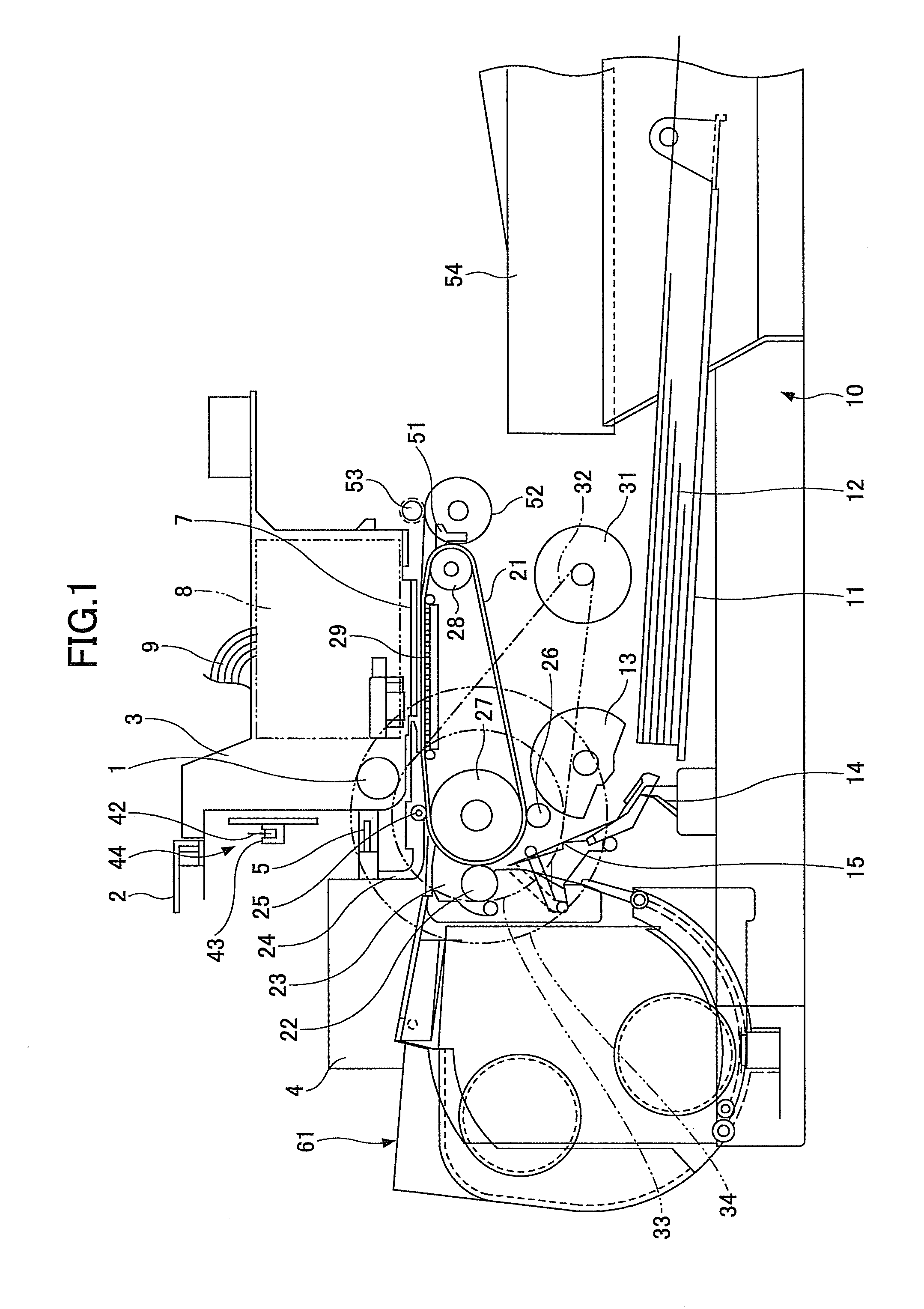
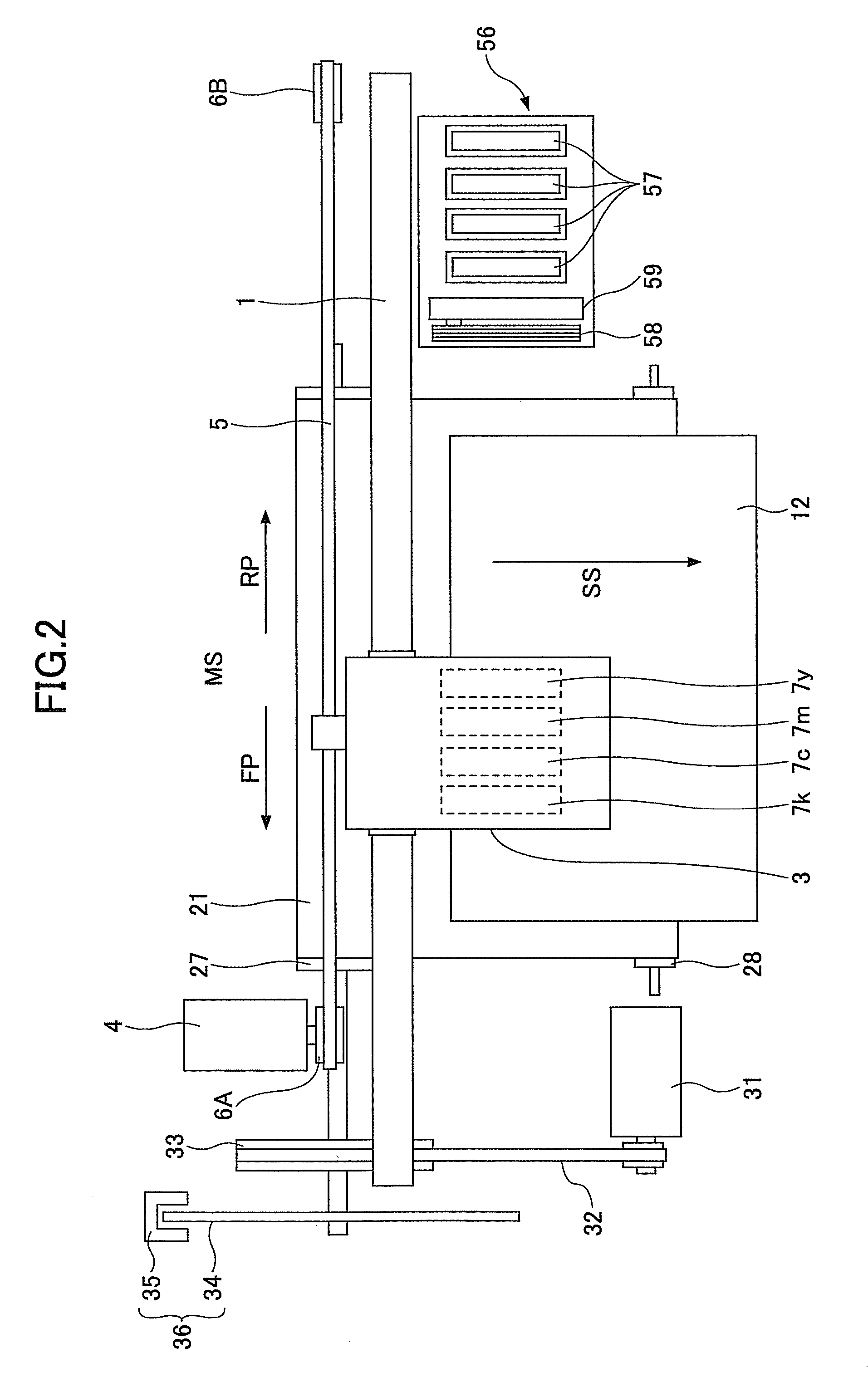
[0055]FIG. 1 is a side view illustrating a structure of an image forming apparatus in a first embodiment of the present invention, and FIG. 2 is a plan view illustrating a structure of the image forming apparatus. The image forming apparatus includes a guide rod 1 and a guide rail 2, which form guide members, and are provided across right and left side plates (not illustrated). A carriage 3 is slidably supported by the guide rod 1 and the guide rail 2, and is free to slide in a main scan direction MS. The carriage 3 is driven by a main scan motor 4 via a timing belt 5 that is provided across a driving pulley 6A and a following pulley 6B, and moves and scans in the main scan direction MS in a forward path FP or a reverse path RP. The main scan motor 4, the timing belt 5, and the pulleys 6A and 6B form a recording head scan part (or recording head scan means).

[0056]Four recording heads 7y, 7c, 7m and 7k, respectively formed by ink-jet heads having nozzles for jetting yellow (Y), cyan ...

second embodiment

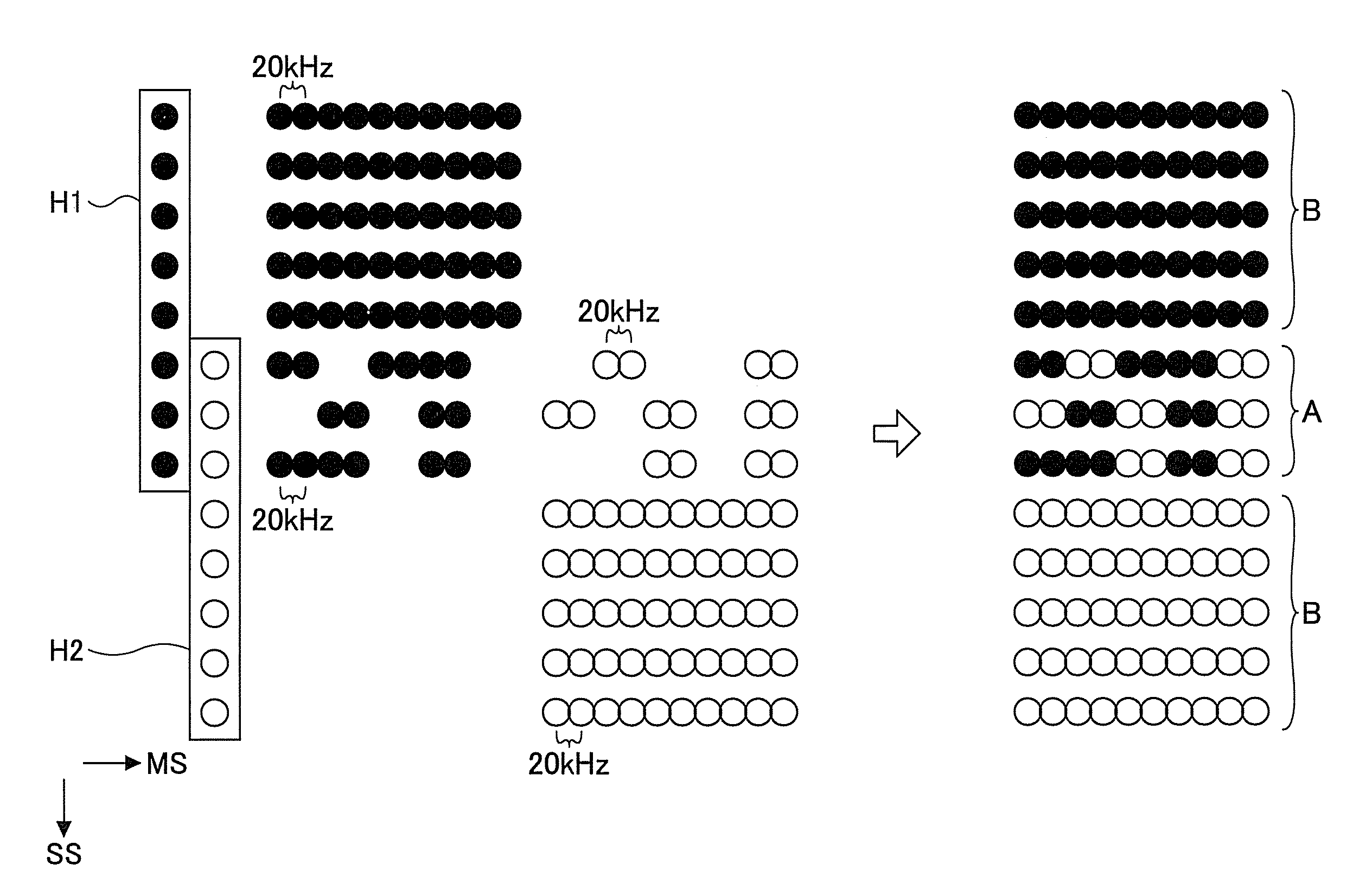
[0193]Next, a description will be given of the image forming apparatus in a second embodiment of the present invention. In this second embodiment, the recording rate of the dots within the overlapping region A is set smaller towards one end (or boundary) of the overlapping region A along the sub scan direction SS. In addition, the number of consecutive dots recorded in the main scan direction MS within the overlapping region A is set smaller towards one end (or boundary) of the overlapping region A along the sub scan direction SS. The sub scan direction SS matches a longitudinal direction of the recording head 7 in which the nozzles are arranged.

[0194]FIGS. 24A and 248 is a diagram illustrating examples in which the dot recording rate decreases towards one end in the sub scan direction SS. In FIGS. 24A and 248, H1P denotes the dots recorded on the recording medium 12 by the head H1, H2P denotes the dots recorded on the recording medium 12 by the head H2, and LRP denotes the landing ...


PUM


Abstract

An image forming apparatus performs a 1-pass recording by a single main scan with respect to a recording medium by a nozzle group including different overlapping nozzles that scan the same overlapping region on the recording medium to record dots. Alternatively, a multi-pass recording is performed by a plurality of main scans with respect to the overlapping region by the same nozzle group or by different nozzle groups. The recording in a central portion of the overlapping region is performed by placing emphasis on the succession or continuity of the dots, while the recording in boundary portions of the overlapping region is performed by placing emphasis on the scattering of the dots.

Description

CROSS REFERENCE TO RELATED APPLICATIONS[0001]This application claims the benefit of Japanese Patent Applications No. 2009-008050 filed on Jan. 16, 2009, No. 2009-252186 filed on Nov. 2, 2009, and No. 2010-004552 filed on Jan. 13, 2010, in the Japanese Patent Office, the disclosures of which are hereby incorporated by reference.BACKGROUND OF THE INVENTION[0002]1. Field of the Invention[0003]The present invention relates to image forming apparatuses, image forming methods and computer-readable storage media for forming images according to the ink-jet recording technique.[0004]2. Description of the Related Art[0005]The ink-jet recording technique enables a high-speed recording on the so-called plain paper without requiring a special fixing process, and the noise generated during the recording is negligibly low. Hence, the ink-jet recording technique is suited for office use. In addition, various systems employing the ink-jet recording technique have been proposed and reduced to practic...

Claims


Application Information

Patent Timeline
Patent Type & Authority Patents(United States)
IPC IPC(8): B41J29/38
CPCB41J2/145B41J2/2132B41J29/38B41J29/393
Inventor TAKAGI, YASUNOBUKIMURA, TAKASHISATOH, TAKUYOSHIDA, MASAKAZUKAMEI, TOSHIHITO
Owner RICOH KK
Features
  • Generate Ideas
  • Intellectual Property
  • Life Sciences
  • Materials
  • Tech Scout
  • Unparalleled Data Quality
  • Higher Quality Content
  • 60% Fewer Hallucinations
Learn More