Solid propellant rocket motor having self-extinguishing propellant grain and systems therefrom

a solid propellant and grain technology, applied in the field of solid propellant rocket motors and systems therefrom, can solve the problems of shutting off process functionalities, inability to control or alter thrust characteristics of solid propellant rockets, and inability to control or alter thrust characteristics

Active Publication Date: 2012-12-25
UNIV OF CENT FLORIDA RES FOUND INC
View PDF6 Cites 14 Cited by
  • Summary
  • Abstract
  • Description
  • Claims
  • Application Information

AI Technical Summary

Problems solved by technology

However, unlike liquid propellant rockets, solid propellant rockets are unable to control or alter their thrust characteristics after ignition by adjusting the amount of fuel entering the area of combustion.
Known composite propellant rocket motors have generally been shut-off by a process of sudden depressurization, but the Present Inventors are not aware of a disclosed shut-off process functional at operational pressures.
Some shut-off processes involve a destructive means of operation, such as requiring physical rupture of the case in some fashion to depressurize the combustion chamber.
This practice has several pitfalls, such as severe structural damage to the motor and uncontrolled burn-off of the remaining solid propellant.
The interceptor is directed toward the attacking missile (the so-called “target”) and preferably hits or explodes in the vicinity of the target, generally causing the target severe damage and perhaps even complete destruction.
To satisfy the extreme requirements of a DACS motor, which can include trajectory adjustment and multiple firings, the solid motor must be able to be extinguished and relit, generally a plurality of times. To date, the extinguishment of burning solid propellants does not occur naturally, so the available technology generally requires a complicated rapid depressurization technique to stop the propellant from burning.

Method used


Image

  • Solid propellant rocket motor having self-extinguishing propellant grain and systems therefrom
  • Solid propellant rocket motor having self-extinguishing propellant grain and systems therefrom
  • Solid propellant rocket motor having self-extinguishing propellant grain and systems therefrom

Examples


Embodiment Construction

[0017]The present invention is described with reference to the attached figures, wherein like reference numerals are used throughout the figures to designate similar or equivalent elements. The figures are not drawn to scale and they are provided merely to illustrate the instant invention. Several aspects of the invention are described below with reference to example applications for illustration. It should be understood that numerous specific details, relationships, and methods are set forth to provide a full understanding of the invention. One having ordinary skill in the relevant art, however, will readily recognize that the invention can be practiced without one or more of the specific details or with other methods. In other instances, well-known structures or operations are not shown in detail to avoid obscuring the invention. The present invention is not limited by the illustrated ordering of acts or events, as some acts may occur in different orders and / or concurrently with o...


PUM

PropertyMeasurementUnit
wt %aaaaaaaaaa
pressuresaaaaaaaaaa
sizeaaaaaaaaaa

Abstract

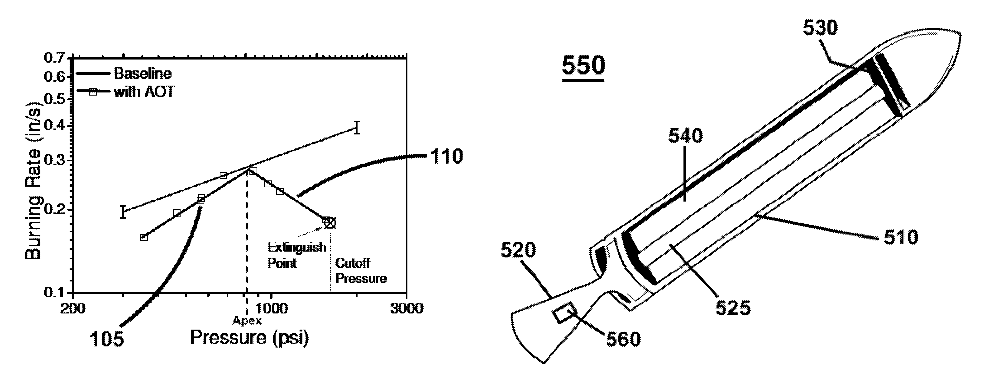
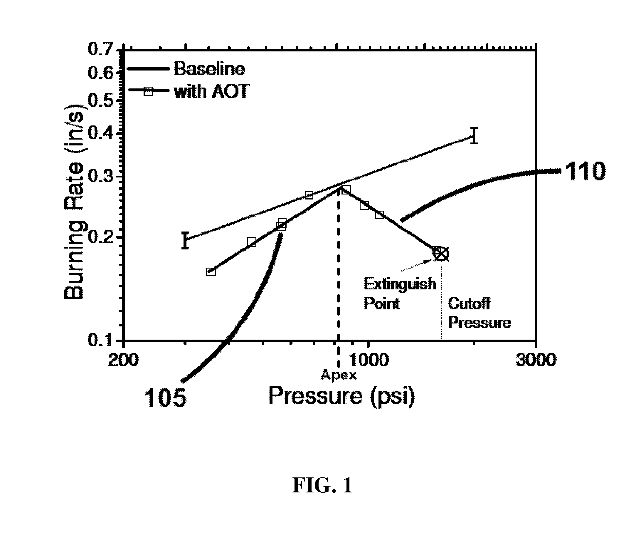
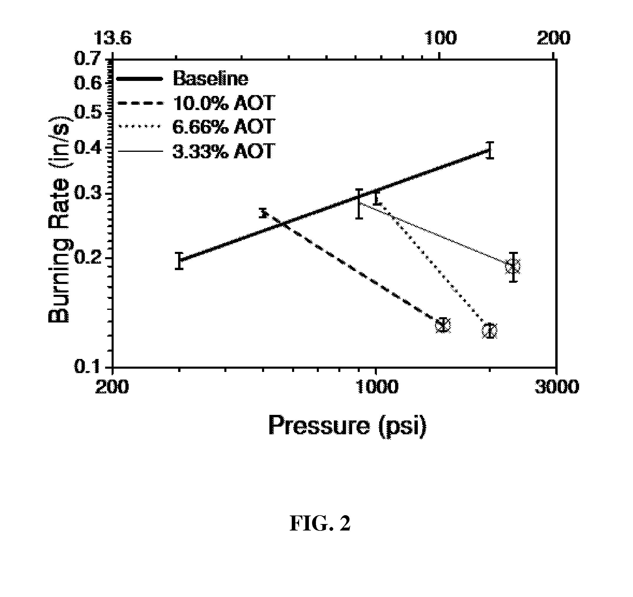
A solid rocket motor includes a combustion chamber bounded by an outer casing, a propellant grain within the combustion chamber, and an igniter within the outer casing for igniting the propellant grain. A nozzle is coupled to the combustion chamber for releasing hot gasses evolved from burning the propellant grain to provide thrust for propelling the solid rocket motor. The propellant grain is a self-extinguishing propellant grain that includes at least one fuel, at least one oxidizing agent, at least one binder, and at least one surfactant that imparts the self-extinguishing property. The propellant grain provides a burning rate as a function of pressure that includes a negative pressure dependence portion, wherein the burning rate in the negative pressure dependence portion decreases with increasing pressure until a cutoff pressure is reached which results in extinguishment of the propellant grain.

Description

CROSS REFERENCE TO RELATED APPLICATIONS[0001]This application claims the benefit of Provisional Application Ser. No. 61 / 040,056 entitled “EXTINGUISHABLE SOLID ROCKET PROPELLANT ROCKET MOTOR” filed Mar. 27, 2008, which is hereby incorporated by reference in its entirety.FEDERAL RIGHTS STATEMENT[0002]The U.S. Government has rights to embodiments of the invention based on Missile Defense Agency contract #HQ0006-05-0023.FIELD[0003]Embodiments of the present invention relate to solid propellant rocket motors and systems therefrom.BACKGROUND[0004]A solid rocket motor or composite propellant rocket motor is a rocket with a motor that uses solid propellants comprising a fuel and an oxidizer. The solid propellant is normally in the form of a propellant grain placed within the interior of the rocket motor (e.g. in the combustion chamber) and burned to produce hot gases which, in turn, exit through the throat and nozzle of the rocket motor at high velocity to provide thrust which propels the r...

Claims


Application Information

Patent Timeline
Patent Type & Authority Patents(United States)
IPC IPC(8): C06D5/00F02K9/00C06B45/00
CPCF02K9/92C06B23/007C06B45/10
Inventor PETERSEN, ERIC L.SEAL, SUDIPTASTEPHENS, MATTHEWREID, DAVID L.CARRO, RODOLPHESAMMET, THOMASLEPAGE, ALEX
Owner UNIV OF CENT FLORIDA RES FOUND INC
Why Eureka
Try Eureka