Pair of pressing jaws for hydraulic or electric pressing tool
- Summary
- Abstract
- Description
- Claims
- Application Information
AI Technical Summary
Benefits of technology
Problems solved by technology
Method used
Image
Examples
first embodiment
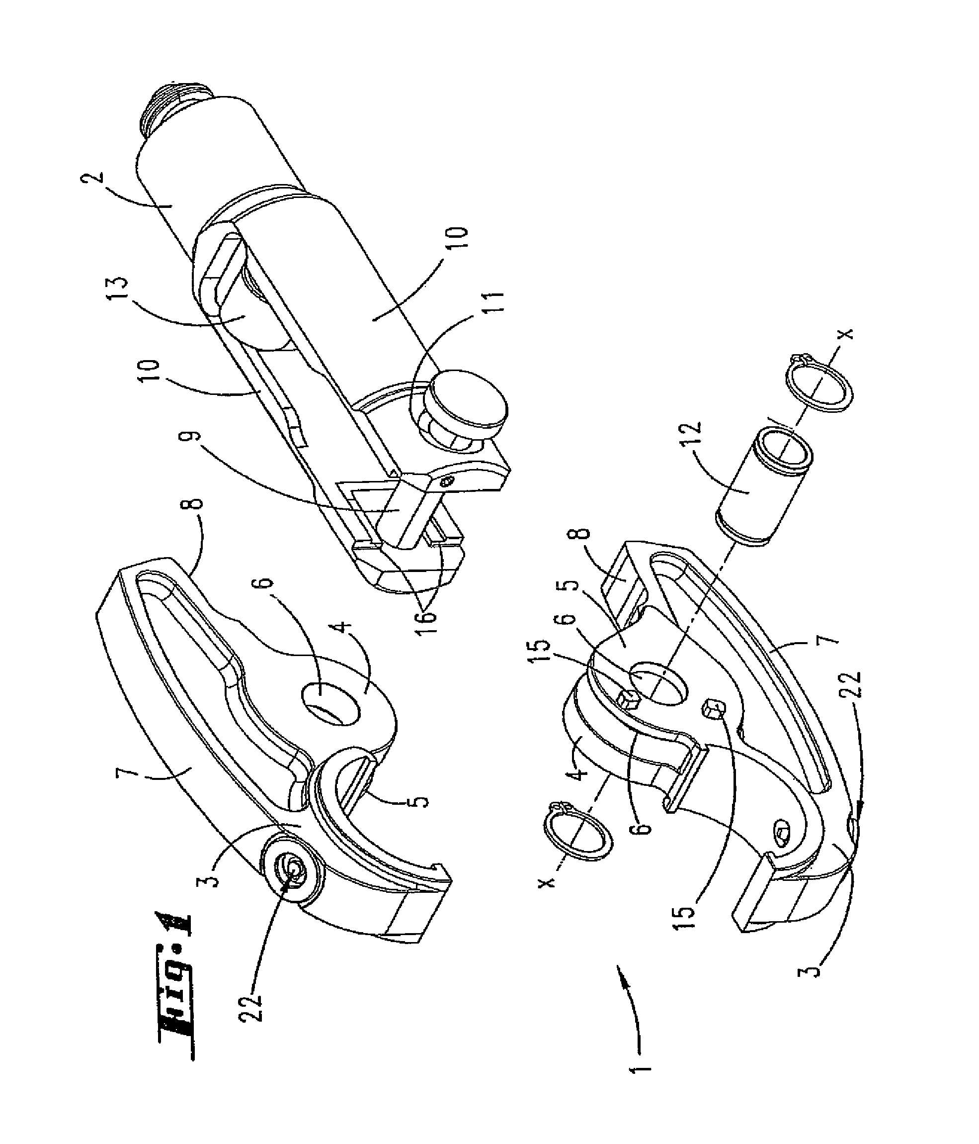
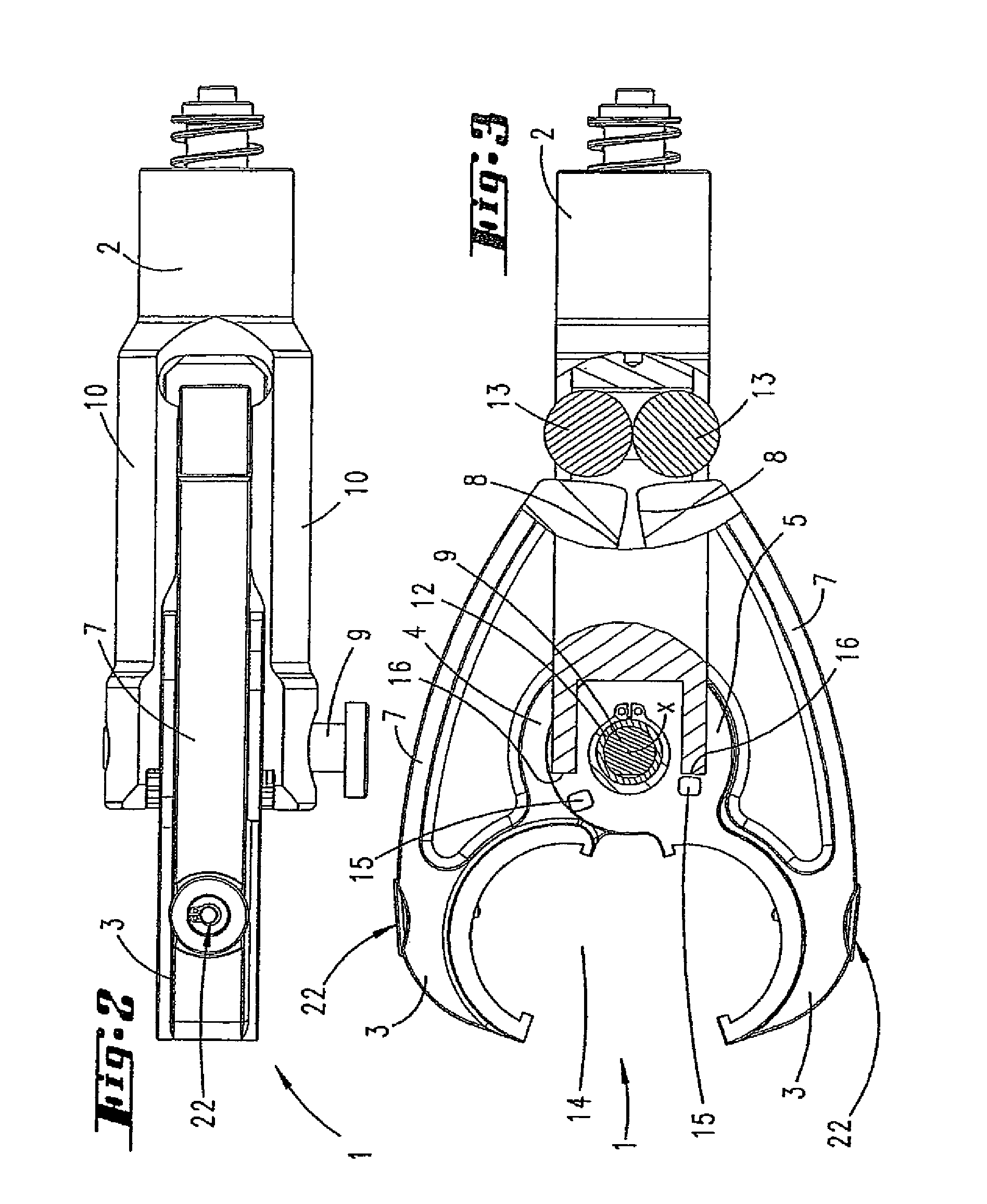
[0049]Illustrated and described, in the first instance with reference to FIG. 1, of a pair 1 of pressing jaws, in a first embodiment, for a hydraulic or electric pressing tool, merely an accommodating neck 2 of the latter, for accommodating a pair 1 of pressing jaws, being shown in the illustrations.
[0050]The two pressing jaws 3 are configured identically to one another and each have two bearing eyes 4, 5 with coaxial bearing openings 6.
[0051]The pressing jaws 3 are part of a pressing lever 7 which, on one side of the bearing opening 6, forms the pressing jaw 3 and, on the other side of the bearing opening 6, forms a curved track 8.
[0052]The bearing eyes 4, 5 of each pressing jaw 3 have different thicknesses, as measured in the axial direction of the bearing openings. The bearing eye 4 is thus approximately three times the thickness of the bearing eye 5.
[0053]The clear distance between the two bearing eyes 4 and 5 corresponds approximately to the thickness of the thicker bearing eye...
second embodiment
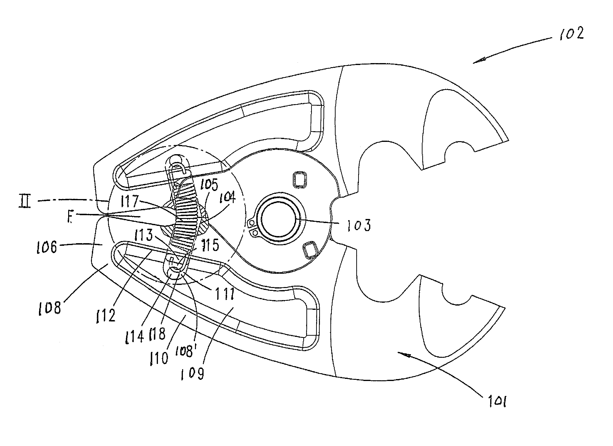
[0063]The pressing jaws 3 of the second embodiment are preloaded into their open position, which is illustrated for example in FIG. 8, a tension spring 17 being provided for this purpose. This tension spring is disposed in order to engage over the separating joint F between the pressing levers 7 of the pressing jaws 3 and is positioned, in each pressing jaw, in an accommodating bore 18 which opens out into that narrow peripheral side of the pressing jaw 3 which is directed toward the separating joint F. The two accommodating bores 18 of the pressing jaws 3 are disposed opposite one another. These accommodating bores 18 open out, at the other end, into bores 19 which pass through the pressing jaw 3, transversely to the direction in which the tension spring 17 extends, in the region of the pressing lever 7. Positioned in each of these bores 19 is a retaining pin 20 which receives the respective end of the tension spring 17 and in this respect, in interaction with the wall of the bore ...
PUM
| Property | Measurement | Unit |
|---|---|---|
| diameter | aaaaa | aaaaa |
| tension | aaaaa | aaaaa |
| thickness | aaaaa | aaaaa |
Abstract
Description
Claims
Application Information
 - R&D
- Intellectual Property
- Life Sciences
- Materials
- Tech Scout
- Unparalleled Data Quality
- Higher Quality Content
- 60% Fewer Hallucinations
Browse by: Latest US Patents, China's latest patents, Technical Efficacy Thesaurus, Application Domain, Technology Topic, Popular Technical Reports.
© 2025 PatSnap. All rights reserved.Legal|Privacy policy|Modern Slavery Act Transparency Statement|Sitemap|About US| Contact US: help@patsnap.com


