Tire valve assembly, system and apparatus for deflating a tire following unauthorized access to a motor vehicle

a technology for deflating tires and motor vehicles, applied in the direction of tyre-inflating valves, functional valve types, tyre measurements, etc., can solve the problems of special equipment not normally accessible to thieves, and achieve the effect of relatively low cost of a self-damaging tire valve assembly for the vehicle owner

Inactive Publication Date: 2012-12-25
TZARUM DROR +1
View PDF14 Cites 2 Cited by
  • Summary
  • Abstract
  • Description
  • Claims
  • Application Information

AI Technical Summary

Benefits of technology

[0017]Since the damaging apparatus is retained in the interior of a tire, a thief cannot detach the damaging apparatus without replacing each tire valve assembly, an operation which is time consuming and which requires specialized equipment not usually accessible to thieves. Employment of self-damaging tire valve assemblies of the present invention therefore considerably increases the anti-theft protection of motor vehicles, and may obviate the need of an anti-theft protection system.
[0022]d) damaging apparatus housed within, or mounted externally to, said valve assembly body and is adapted, following generation of an activation signal upon access to a motor vehicle by an unauthorized person, to selectively damage said body and said grommet, without damaging the tire or tire rim, to such a degree that air escapes from the corresponding tire.
[0023]Since a tire or tire rim is not damaged after activation of the damaging apparatus, the cost of a self-damaging tire valve assembly to a vehicle owner is relatively low. Further savings may be realized by reusing the damaging apparatus in conjunction with an intact tire valve assembly after a first tire valve assembly has been damaged by said damaging apparatus.
[0055]The first valve core is adapted to permit the introduction of air to the tire interior via said first passageway when actuated and to prevent the discharge of air from the tire interior when not actuated and said occluding element is adapted to permit the discharge of air externally to the tire from the tire interior via said second passageway when actuated and to prevent the discharge of air when not actuated. The activation device which is capable of contacting said occluding element is adapted to displace the same and to permit the flow of air through said second passageway.
[0057]In one embodiment, the valve assembly comprises a valve stem formed with external threading, a valve core installed within a bore formed within said stem, a conical grommet, a nut threadedly engaged with said valve stem threading and adapted to press said grommet onto the rim to prevent air leakage from the tire interior, and a first gear in engagement with, or connected to, a component of the valve assembly, and in engagement with a second gear driven by a motor which is disposed within the housing, The motor is operable following transmission of the activation signal, causing the valve assembly to be displaced towards the tire interior and to expose the rim aperture, whereby to deflate the tire.

Problems solved by technology

The term “unauthorized access” as referred to herein means an operation performed without authorization of the owner of the motor vehicle or a designated representative thereof that compromises the security or safety of, or the ability to use, the motor vehicle, such as igniting the engine without use of a key, breaking into the motor vehicle while damaging a structural element thereof, e.g. a window, towing the motor vehicle, detaching or removing the anti-theft protection system of the motor vehicle, and the like.
Since the damaging apparatus is retained in the interior of a tire, a thief cannot detach the damaging apparatus without replacing each tire valve assembly, an operation which is time consuming and which requires specialized equipment not usually accessible to thieves.

Method used


Image

  • Tire valve assembly, system and apparatus for deflating a tire following unauthorized access to a motor vehicle
  • Tire valve assembly, system and apparatus for deflating a tire following unauthorized access to a motor vehicle
  • Tire valve assembly, system and apparatus for deflating a tire following unauthorized access to a motor vehicle

Examples


Embodiment Construction

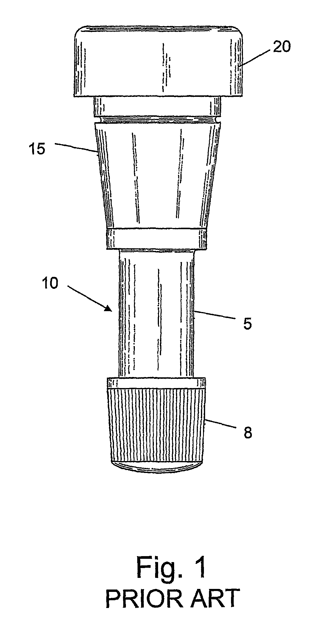
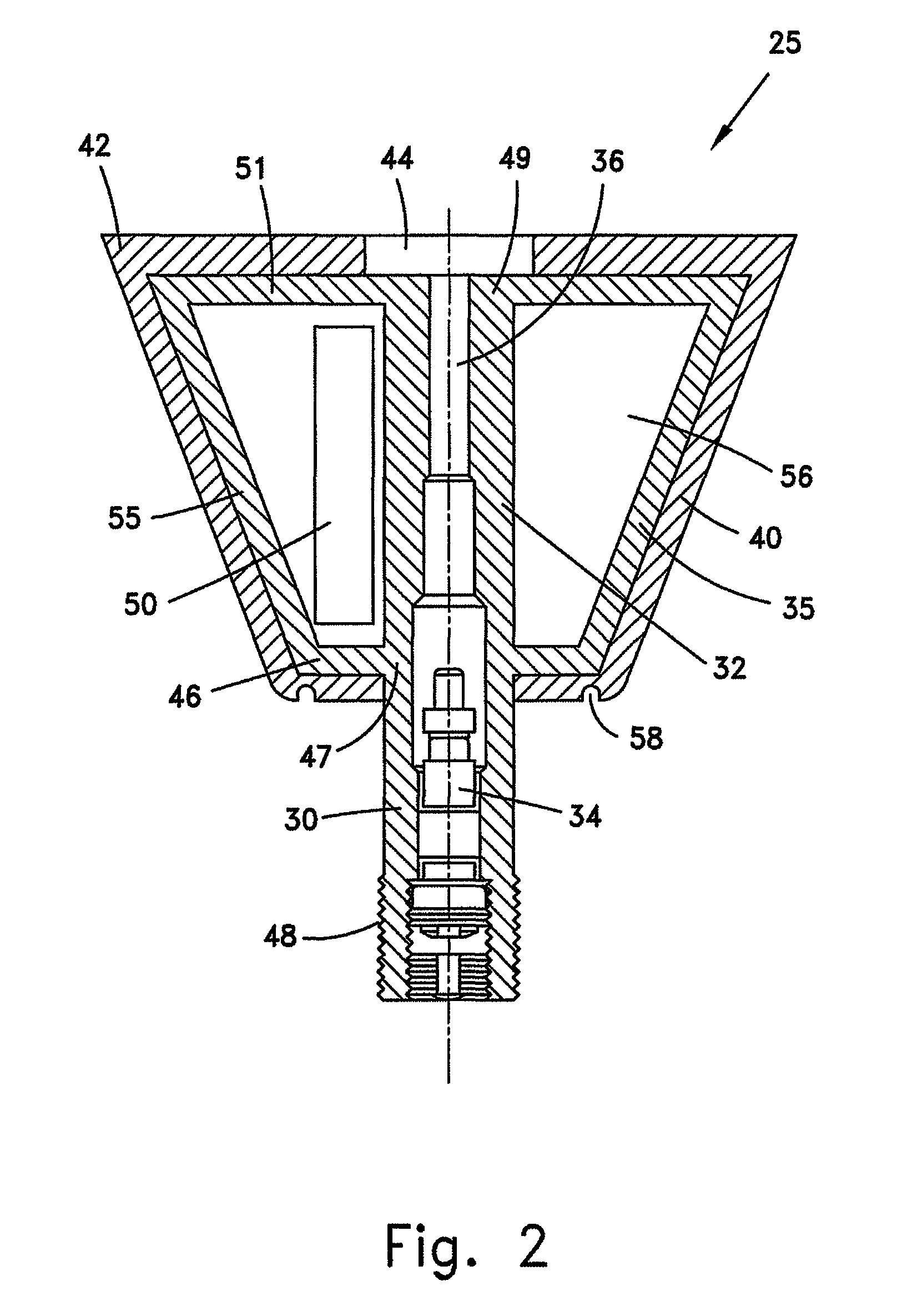
[0072]The present invention relates to an apparatus and system for deflating a tire following unauthorized access to a motor vehicle. While some prior art tire deflating devices cause irreversible damage to the tires following unauthorized access to a motor vehicle, the use of the present invention leaves all tires and all tire rims intact so that they may be reused. The apparatus includes a novel tire valve assembly which includes means for damaging the body and grommet thereof following ignition of the engine by an unauthorized person, as will be explained hereinafter, to such a degree that air escapes from the corresponding tire, thereby disabling the vehicle. After the tire is deflated, a new undamaged valve assembly may be easily mounted to the wheel rim, by which the tire may be inflated. While the mounting of many prior art tire deflating devices require modification to the corresponding wheel rims, wheel rim modification is unnecessary when the valve assembly of the present ...


PUM


Abstract

Apparatus deflates a tire following unauthorized access to a motor vehicle. In one embodiment, a self-damaging tire valve assembly is capable of being damaged to such a degree by damage inflicting apparatus in close proximity to the valve assembly that air escapes from the corresponding tire. An activation device housed within the damage inflicting apparatus, when activated, following unauthorized access of a motor vehicle is able to damage the body and grommet of the valve assembly without damaging the tire rim. In one embodiment, a processor transmits an activation signal to a wireless switch following reception of an unauthorized access signal when the motor vehicle is in an armed state. In one embodiment, a housing containing the tire deflating apparatus is in contact with the valve assembly, and the tire deflating apparatus is activated to cause the tire to be deflated following unauthorized access of the motor vehicle.

Description

FIELD OF THE INVENTION[0001]The present invention relates to the field of car theft deterrent devices. More particularly, the invention relates to an apparatus and system for disabling a vehicle following unauthorized access thereto by deflating one or more tires.BACKGROUND OF THE INVENTION[0002]Automobile anti-theft devices for causing deflation of tires when the engine is started without use of the ignition key are well known. For example, U.S. Pat. No. 3,688,257 discloses an apparatus which comprises a probe extending through a bore in the corresponding wheel rim and adapted to strike, following tire rotation, against a plunger, which is retractable by means of an ignition-energized solenoid. When the solenoid is not energized, the probe strikes the extended plunger and breaks, whereby an opening is produced and air escapes to deflate a tire. The drawback of such an apparatus is that the rim needs to be modified by producing a bore therethrough, in order to accommodate the probe....

Claims


Application Information

Patent Timeline
Patent Type & Authority Patents(United States)
IPC IPC(8): B60R25/00
CPCB60R25/096B60R2325/101Y10T137/1632Y10T137/1647Y10T137/3786B60R2011/0003B60R2011/004B60Y2400/30
Inventor TZARUM, DRORTZARUM, ASHER
Owner TZARUM DROR
Why Eureka
Try Eureka