Snap-on coupling for connecting a fluid pipe to a rigid end fitting with a connection indicator and method of inspecting this connection

a technology of fluid pipe and indicator, which is applied in the direction of pipe couplings, hose connections, hose/joint/fittings, etc., can solve the problems of inability to hear the operator's character noise and the inability to hear the audible indicator of a correct connection in a hostile environment with background nois

Active Publication Date: 2012-12-25
HUTCHINSON SA
View PDF16 Cites 18 Cited by
  • Summary
  • Abstract
  • Description
  • Claims
  • Application Information

AI Technical Summary

Benefits of technology

[0011]be retained in the extended position before the connection is made, on the one hand by being prevented from occupying the depressed position by said retention arms which bear on said bottom stops and on the other hand by resisting its complete extraction from the sleeve by locking means formed on the legs which bear on the underside of top stops of this sleeve,
[0034]It will be observed that this releasing of the connection can be easily brought about in a single manual action by the operator by pressing as described above at these two diametrically opposite locations on the sleeve.

Problems solved by technology

The operator making the connection can be confident that the connection is correctly made when the two elastic legs return to their initial positions after the peripheral projection on the end fitting has passed between them, because this produces a characteristic noise which the operator can hear.
However, this audible indicator of a correct connection may not be heard by an operator working in a hostile environment with background noise.

Method used


Image

  • Snap-on coupling for connecting a fluid pipe to a rigid end fitting with a connection indicator and method of inspecting this connection
  • Snap-on coupling for connecting a fluid pipe to a rigid end fitting with a connection indicator and method of inspecting this connection
  • Snap-on coupling for connecting a fluid pipe to a rigid end fitting with a connection indicator and method of inspecting this connection

Examples


Embodiment Construction

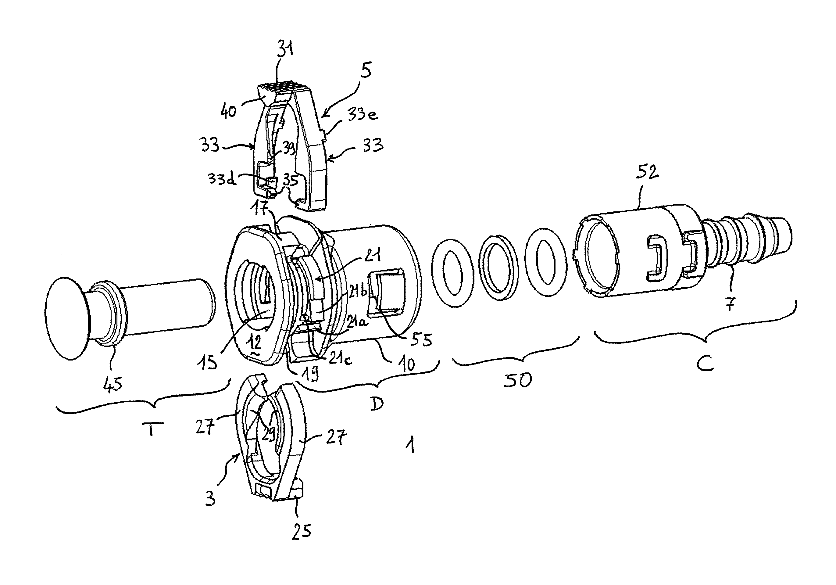
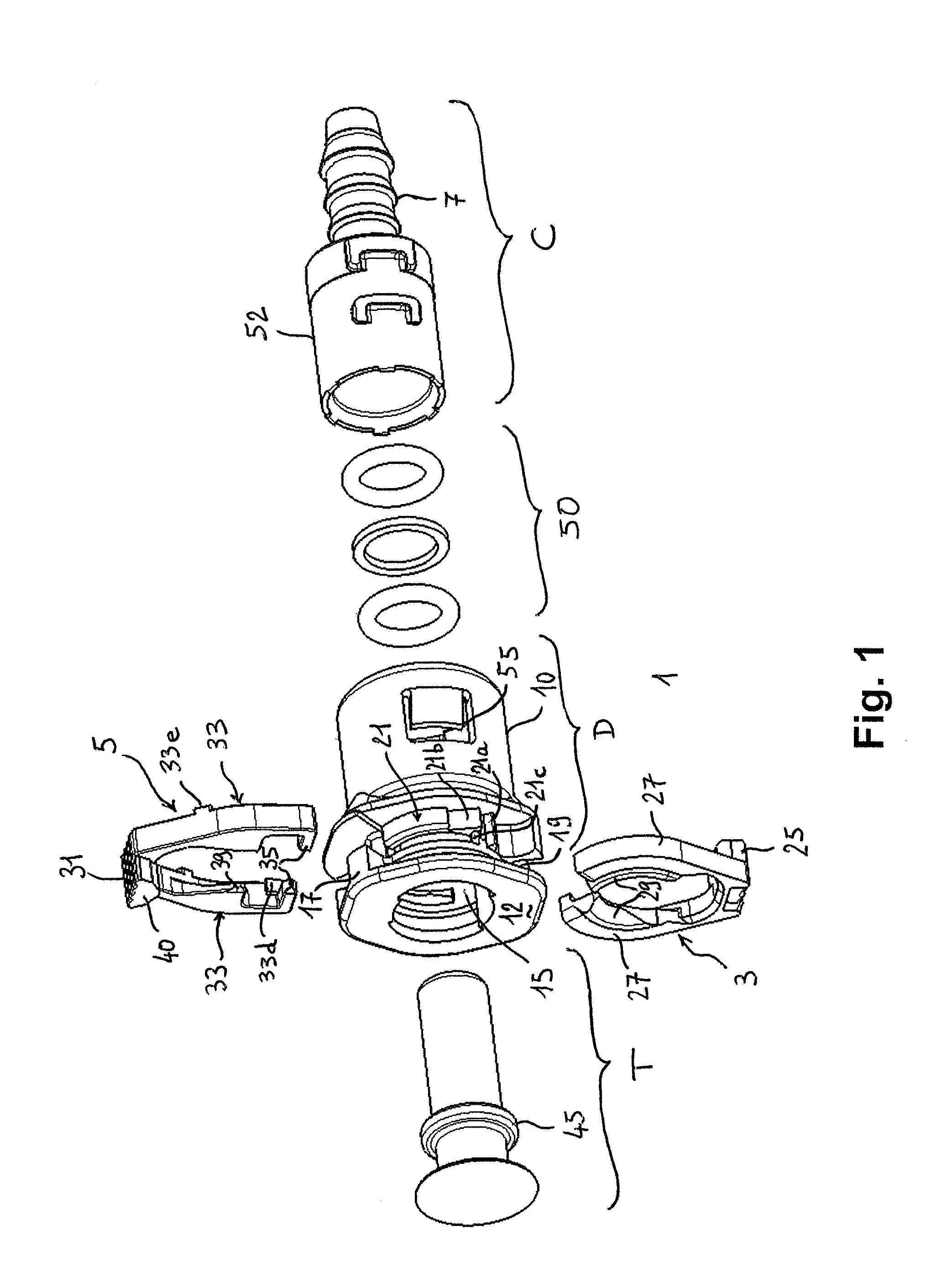
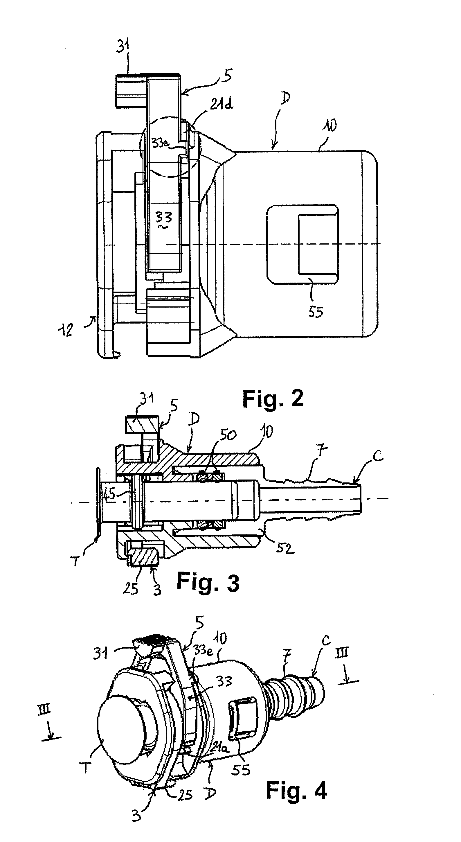
[0056]The snap-on coupling 1 as illustrated in FIG. 1 between a fluid pipe C and a tubular end fitting T comprises a body in the shape of a sleeve D mounted in a fixed manner via a retention device on one end of the pipe C, a locking member 3 for the end fitting T in the sleeve D, and a visual indicator 5 of correct connection between the end fitting T and the sleeve D. The pipe C is usually flexible and is connected leaktightly by forcing its end onto a fir-tree end 7 for example which continues one end of the sleeve D, this fir-tree end constituting the aforementioned retention device. The end fitting T possesses toward its free end a peripheral connection projection or collar 45 which, when the end fitting T is inserted into the sleeve D, engages first with the locking member 3 and then with the indicator 5.

[0057]The coupling 1 also includes means for creating a seal between the end fitting T and the pipe C. These sealing means may be annular gaskets 50 for example mounted or ove...


PUM


Abstract

The present invention relates to a snap-on coupling between a fluid pipe and a rigid tubular end fitting, this coupling having a sleeve mounted on a pipe to be coupled to an end fitting that has a peripheral connecting projection, a locking member engaging with this projection to retain the end fitting in the sleeve, and a visual indicator which engages with the projection behind the locking member and occupying an extended position and a depressed position in the sleeve, the member and the indicator each having a head and two elastically deformable side legs, each leg of the indicator having a retention arm engaging with a lower side tooth and with a bottom stop, both formed on the corresponding side of the sleeve, when the indicator occupies the depressed and extended positions, respectively.

Description

CROSS REFERENCE TO RELATED APPLICATIONS[0001]This application claims priority from French application Ser. No. 09 / 02113, filed Apr. 30, 2009, which is hereby incorporated herein in its entirety by reference.FIELD AND BACKGROUND OF THE INVENTION[0002]The present invention relates to a snap-on coupling for connecting a low-pressure fluid pipe to a rigid tubular end fitting, particularly for a fuel supply line or for a brake power line for a vehicle driven by a heat engine. More specifically, the invention relates to such a coupling fitted with a visual indicator for showing correct connection between this end fitting and a sleeve of this coupling into which this pipe is inserted, as well as to a method of visually inspecting this connection.[0003]A snap-on coupling for connecting a fluid pipe to a rigid tubular end fitting is described for example in FR-A1-2 795 156 in the present Applicant's name. That coupling comprises among other things a sleeve mounted in a fixed position on one ...

Claims


Application Information

Patent Timeline
Patent Type & Authority Patents(United States)
IPC IPC(8): F16L35/00
CPCF16L37/088F16L37/144F16L2201/10F16L37/0885
Inventor GILLET, DAMIENMILANINI, LUC
Owner HUTCHINSON SA
Why Eureka
Try Eureka