Compact device for mixing fluids in a downflow reactor

a technology of fluid mixing and downflow reactor, which is applied in the direction of transportation and packaging, physical/chemical process catalysts, and aromatic hydrocarbon hydrogenation. it can solve the problems of non-selective reaction, large box complex, and prematurely reducing catalyst activity

Active Publication Date: 2012-12-25
INST FR DU PETROLE
View PDF6 Cites 14 Cited by
  • Summary
  • Abstract
  • Description
  • Claims
  • Application Information

AI Technical Summary

Benefits of technology

[0007]A first object of the invention is to provide a compact device for mixing fluids in a downflow reactor.

Problems solved by technology

These hot spots can prematurely decrease the catalyst activity.
They also lead to non-selective reactions.
These boxes are generally very complex.
The main drawbacks of this type of system are the complexity of development and implementation, the induced pressure drop and more particularly the overall dimensions (room taken up in the reactor).
This device allows to overcome some drawbacks of the various systems of the prior art, but it remains very bulky.

Method used


Image

  • Compact device for mixing fluids in a downflow reactor
  • Compact device for mixing fluids in a downflow reactor
  • Compact device for mixing fluids in a downflow reactor

Examples


example 1

Analysis of the Fluid Flow at the Level of the Annular Chamber According to the Invention

[0053]The flow of two fluids in the annular mixing chamber according to the invention is simulated using a fluid mechanics software (Fluent 6.3, developed by ANSYS Inc., Canonsburg, USA). The numerical simulations concerned the analysis of the mixing phenomena:

[0054](a) in the annular mixing chamber,

[0055](b) at the outlet of said chamber.

[0056]The characteristics of the various annular mixing chambers tested and the experimental simulation conditions are given in Table 1 hereafter.

[0057]These simulations are carried out considering the most unfavourable conditions, i.e. the case where the fluids (liquid water and gaseous nitrogen) are not mixed at all at the toroid inlet. The following configuration is thus imposed on the software: the fluids are delivered at two clearly distinct temperatures T1 and T2 at the toroid inlet, so that half of the toroid inlet section is at temperature T1 and the ot...

example 2

Analysis of the Fluid Flow at the Level of the Predistribution Plate According to the Invention

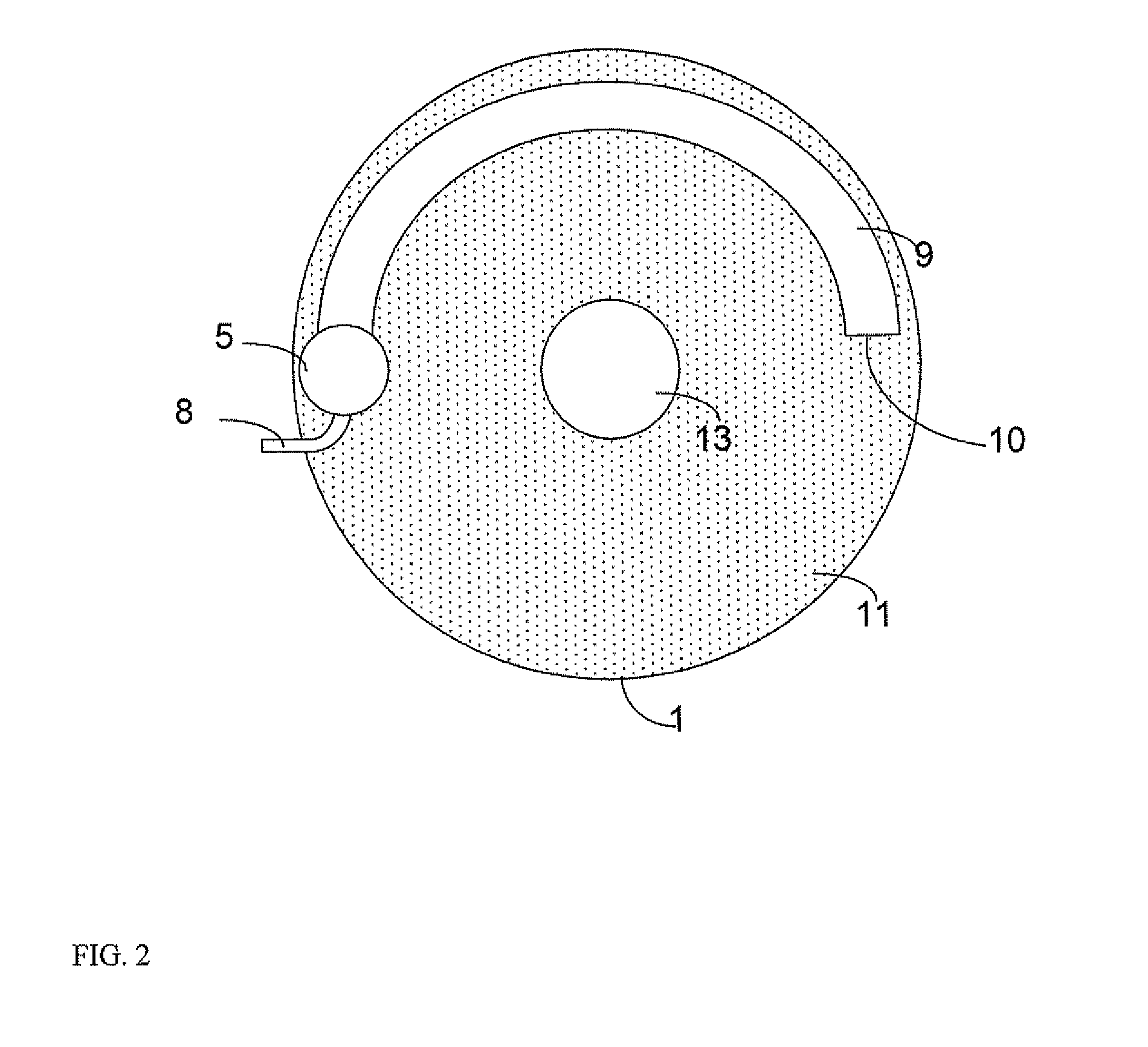
[0066]We want to determine the mixing efficiency generated in the mixing device according to the invention at the level of the predistribution plate. The fluid flow on the predistribution plate is therefore simulated with the fluid mechanics software (Fluent 6.3, developed by ANSYS Inc., Canonsburg, USA). The characteristics of the various mixing devices and the experimental conditions tested are summed up in Table 3. The simulations are performed with single-phase flows, i.e. in the absence of a gas phase. They are thus representative of the case where the quench fluid is liquid and only the liquid phases are to be mixed.

[0067]

TABLE 3Height ofLiquidliquid on theToroidToroidReactorphasepre-diameterlengthdiametervelocityTemperatureTemperaturedistribution(m)(° degrees)(m)(m / s)T1T2plate in mToroid0.190°0.480.52733230.12No. 1Toroid0.190°0.4812733230.12No. 2Toroid0.190°0.480.22733230.12No. 3Tor...

example 3

Cold Model Tests

[0075]By way of non limitative example, mixing efficiency measurements were carried out with a mixing device according to the invention arranged in a reactor. The experimental conditions are as follows:

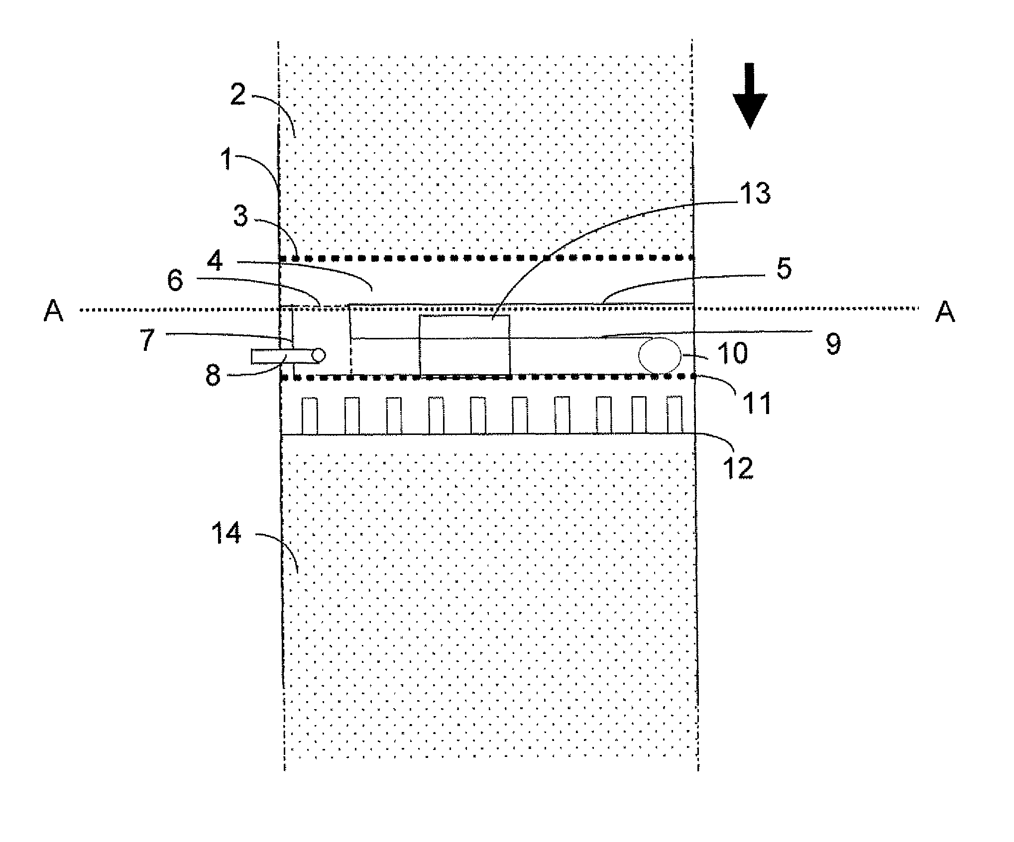
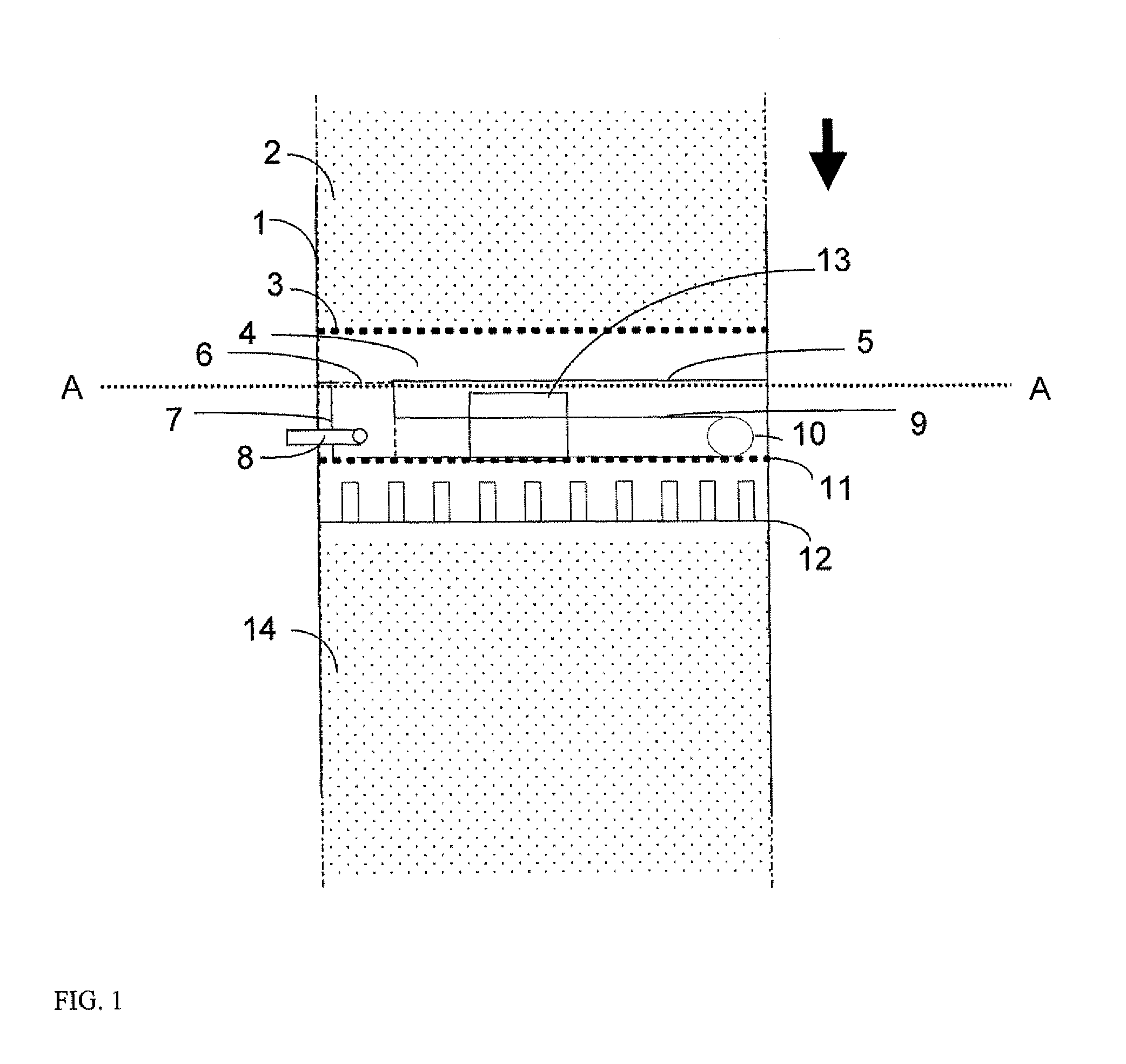
[0076]A 480 mm-diameter reactor is divided into two identical sectors in the upper part thereof. The two sectors are identically supplied with gas (air) and liquid (water). The height of the sectors is 500 mm. The sectors are supplied with fluids at different temperatures T1 (283 K) and T2 (330 K). The gathering baffle is arranged below the granular bed, carried by the support grid. The distance between the support grid and the gathering baffle is 100 mm. The vertical gathering line is 150 mm in height and 100 mm in diameter. The structural characteristics of the various mixing toroids tested are given in Table 5. The quench fluid (water) injection tube is 20 mm in diameter. The predistribution plate is provided with a 4 cm-diameter and 25 cm-high central chimney. The ...


PUM

PropertyMeasurementUnit
distance d2aaaaaaaaaa

Abstract

A compact device for mixing fluids in a downflow reactor comprising at least one substantially horizontal gathering device provided with a vertical gathering line intended to receive the fluids, at least one injection device arranged in the gathering line, an annular mixing chamber located downstream from the gathering means in the direction of circulation of the fluids, the mixing chamber comprising an inlet end directly connected to the gathering line and an outlet end for passage of the fluids, and a horizontal predistribution plate comprising at least one chimney, the plate being located downstream from the mixing chamber at a distance d2, in the direction of circulation of the fluids. The reactor is especially useful for exothermic reactions, e.g. hydrotreatment, hydrodesulfurization, hydrodenitrogenation, hydrocracking, hydrogenation and hydrodearomatization reactions.

Description

FIELD OF THE INVENTION[0001]The present invention relates to a compact device for mixing fluids in a downflow reactor and to the use thereof for carrying out exothermic reactions. The invention also relates to a reactor comprising a compact mixing device. The invention applies to the sphere of exothermic reactions and more particularly to hydrotreatment, hydrodesulfurization, hydrodenitrogenation, hydrocracking, hydrogenation and hydrodearomatization reactions.BACKGROUND OF THE INVENTION[0002]Exothermic reactions carried out in refining and / or petrochemistry require cooling by an additional fluid to prevent thermal runaway of the reactor in which they are conducted. It is also necessary to keep a homogeneous temperature gradient within the reactor in order to prevent the existence of hot spots in the catalyst bed. These hot spots can prematurely decrease the catalyst activity. They also lead to non-selective reactions. It is therefore important to hove at least one mixing chamber in...

Claims


Application Information

Patent Timeline
Patent Type & Authority Patents(United States)
IPC IPC(8): B01J8/04B01J10/00
CPCB01J8/0453B01J8/0492C10G47/00C10G45/02C10G45/44B01J2208/00362B01J2208/00371B01J8/02B01J19/00B01F25/40
Inventor AUGIER, FREDERICDARMANCIER, DENISBOYER, CHRISTOPHE
Owner INST FR DU PETROLE
Why Eureka
Try Eureka