
Optical information recording apparatus, optical information recording method, optical information recording/reproducing apparatus and optical information recording/reproducing method

a technology of optical information and recording equipment, applied in the direction of optical recording/reproducing/erasing methods, recording signal processing, instruments, etc., can solve the problems of inconvenient consumption of dynamic range in hologram recording media, inability to improve recording density, and inability to achieve constant transmissivity, the effect of improving the digital density

Inactive Publication Date: 2012-12-25
HITACHI CONSUMER ELECTRONICS CORP
View PDF19 Cites 0 Cited by
  • Summary
  • Abstract
  • Description
  • Claims
  • Application Information

AI Technical Summary

Benefits of technology

[0013]An object of this invention is to provide an encoding method capable of improving the recording density while keeping the transmissivity constant among different pages.
[0015]In the recording of digital information using holography, this invention allows for improvement of the digital density while keeping the transmissivity constant among different pages.

Problems solved by technology

These methods however, have a drawback of consuming a four-bit area to produce 2 bits of information and therefore being unable to improve the recording density.
This difference in transmissivity causes different pages, when reproduced, to have different levels of reproduced image brightness, giving rise to a possibility that an erroneous decision may be made when the reference values for binarization decision are equal.
There is another problem that consumption of dynamic range in a hologram recording medium is not constant.

Method used


Image

  • Optical information recording apparatus, optical information recording method, optical information recording/reproducing apparatus and optical information recording/reproducing method
  • Optical information recording apparatus, optical information recording method, optical information recording/reproducing apparatus and optical information recording/reproducing method
  • Optical information recording apparatus, optical information recording method, optical information recording/reproducing apparatus and optical information recording/reproducing method

Examples


embodiment 1

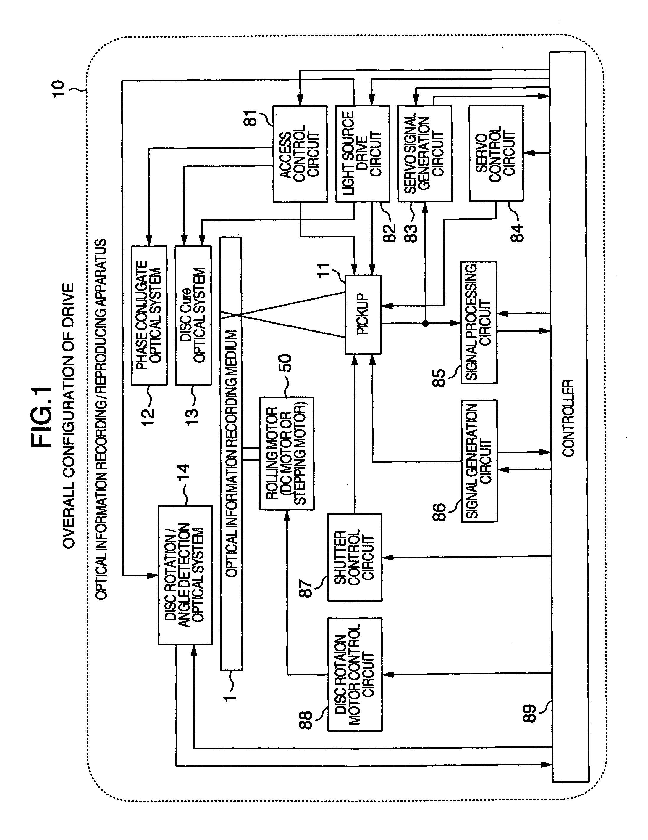
[0030]FIG. 1 shows an overall configuration of the optical information recording / reproducing apparatus to record and / or reproduce digital information by using holography.

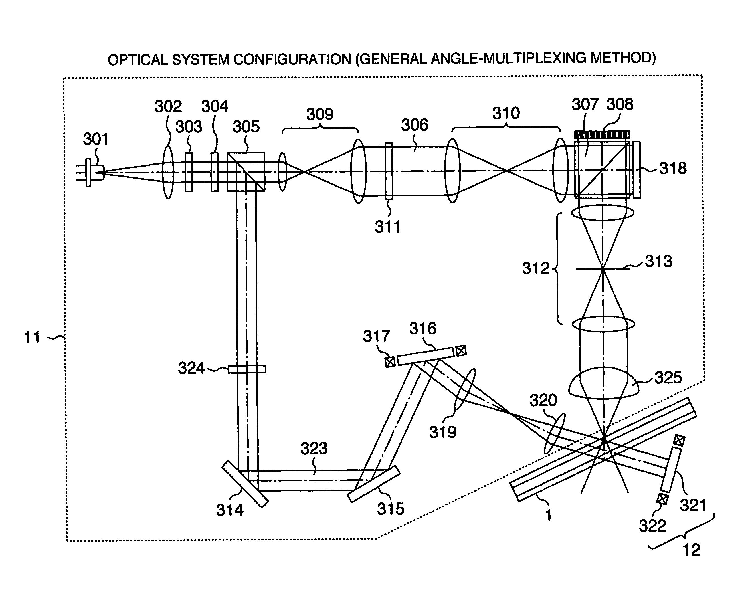
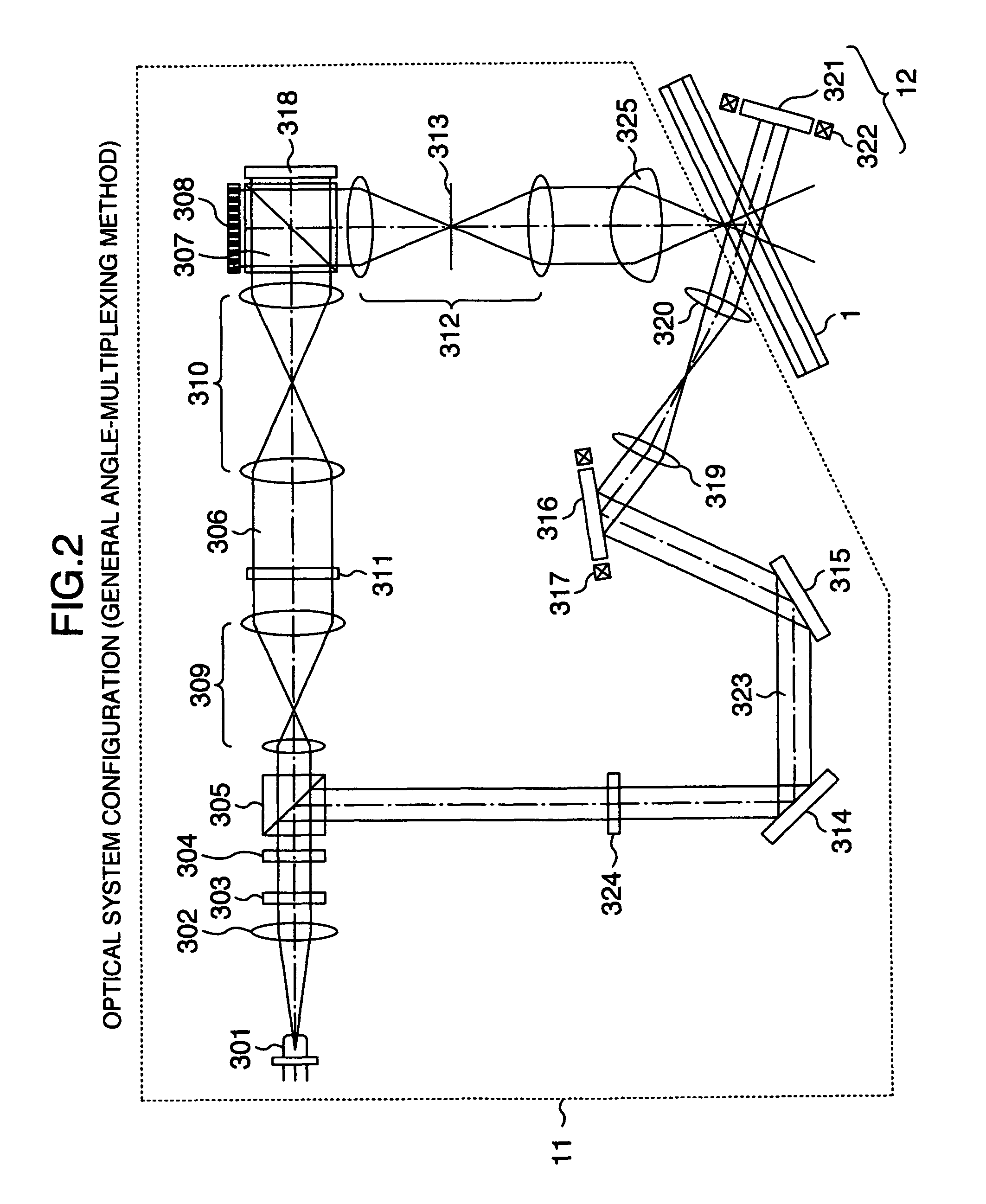
[0031]The optical information recording / reproducing apparatus 10 has a pickup 11, a phase conjugate optical system 12, a disc-cure optical system 13, a disc rotation angle detecting optical system 14 and a rotating motor 50. The optical information recording medium 1 can be turned by the rotating motor 50.

[0032]The pickup 11 emits a reference beam and a signal beam to the optical information recording medium 1 to record digital information by using holography.

[0033]At this time, the information signal to be recorded is sent by a controller 89 through a signal generation circuit 86 to a spatial light modulator described later in the pickup 11 where the signal beam is modulated by the spatial light modulator.

[0034]When the recorded information in the optical information recording medium 1 is reproduced, a phase conjug...

embodiment 2

[0070]The second embodiment differs from embodiment 1 in the 2-mensional data generation method of S306 and the data reproducing method of S317. FIG. 7 shows a detailed operation flow of S306 in FIG. 3B. FIG. 8 shows a detailed operation flow of S317 in FIG. 3C. FIGS. 9A-9F show examples of processing.

[0071]First, a detailed operation during recording will be explained. When the signal generation circuit 86 receives one page of recording data (S701) (FIG. 9A), it modulates data strings by using a modulation table (S702). Next, the data is divided into units of N bits, to each of which a control bit is added (S703) (FIG. 9B). The control bit is one bit in this embodiment but may be multiple bits. First, assuming that a control bit at a certain position is “0” (S704), a DSV up to the next control bit is calculated (S705). It is desired that the DSV be a sum value not only for the data between the control bits but also for all data up to that control bit. Next, when the control bit is ...

embodiment 3

[0077]This embodiment differs from embodiment 1 in the control bit determination rule in S410. In embodiment 1, the DSVs calculated from S406 to S409 are compared and the control bit added in S403 is determined so as to make the DSV close to 0 (S410). In this embodiment, the control bit is determined so as to make the DSV close to a preset target value (S1010).

[0078]Further, to make it easy to shift the DSV in a certain direction, it is useful to modulate the data in advance so as to make the ratios of “0” and “1” of the NRZI-modulated data uneven. For example, in the modulation operation of S1002 in FIG. 10, the modulation is executed using a modulation table such as one shown in FIG. 11A. This operation is characterized in that the modulated data has “1” appear the even number of times, which, when the data is NRZI-modulated, makes the frequencies of appearance of “0” and “1” differ. Although the use of this table renders the ratio of “0” and “1” uneven, the method of modulation i...


PUM

PropertyMeasurementUnit
brightnessaaaaaaaaaa
incident angleaaaaaaaaaa
recording densityaaaaaaaaaa

Abstract

An optical information recording / reproducing apparatus using holography comprises a signal generation unit that modulates input data, adds at least one control bit to each group of N bits, performs an NRZI-modulation on the modulated data, determines the at least one control bit such that a digital sum value of the NRZI-modulated data is 0, performs NRZI modulation on the data whose at least one control bit was determined, and rearranges the data to generate 2-dimensional data; a pickup that records the 2-dimensional data in a hologram disc and reproduces the 2-dimensional data from the hologram disc; and a signal processing unit that corrects the 2-dimensional data reproduced by the pickup, performs NRZI-modulation on the 2-dimensional data that has undergone a binarization operation, removes the at least one control bit added during the recording, and demodulates the data according to a modulation rule used during the recording.

Description

INCORPORATION BY REFERENCE[0001]The present application claims priority from Japanese application JP2008-131454 filed on May 20, 2008, the content of which is hereby incorporated by reference into this application.BACKGROUND OF THE INVENTION[0002]The present invention relates to an apparatus and a method for recording information on and / or reproducing information from optical information recording media by using holography.[0003]Optical disc products with a recording density of about 50 GB are being commercialized that are based on Blu-ray Disc (BD) standard and High Definition Digital Versatile Disc (HD DVD) standard using a blue semiconductor laser.[0004]Optical discs are expected to have an increased capacity of as large as 100 GB to 1 TB, comparable to that of HDD (Hard Disc Drive), in the future.[0005]However, to realize such an ultrahigh density with the current optical discs, a novel storage technology is required, different from the conventional trend of high density technol...

Claims


Application Information

Patent Timeline
Patent Type & Authority Patents(United States)
IPC IPC(8): G11B7/00
CPCG11B7/0065G11B20/1426G11B2020/1457G11B2020/1469G11B2220/2504
Inventor NAKAMURA, YUSUKE
Owner HITACHI CONSUMER ELECTRONICS CORP
Learn More