
Loudspeaker driver suspension

a technology for loudspeaker drivers and suspensions, applied in the direction of diaphragm mounting/tensioning, electrical transducers, electrical apparatus, etc., can solve problems such as stress concentration and unwanted deformation, and achieve the effect of reducing the deficiencies of known loudspeaker drivers

Active Publication Date: 2012-12-25
PARADIGM ELECTRONICS
View PDF17 Cites 13 Cited by
  • Summary
  • Abstract
  • Description
  • Claims
  • Application Information

AI Technical Summary

Benefits of technology

[0022]Advantageously, the undulations in the roll suspension minimize undesirable compressive buckling load, allowing controlled bending load while the smooth transition between the lower cross-section and the higher cross-section reduces the wrinkling / buckling effects.

Problems solved by technology

Transitions between these corrugations would lead to stress concentrations and unwanted deformation.

Method used


Image

  • Loudspeaker driver suspension
  • Loudspeaker driver suspension
  • Loudspeaker driver suspension

Examples


Embodiment Construction

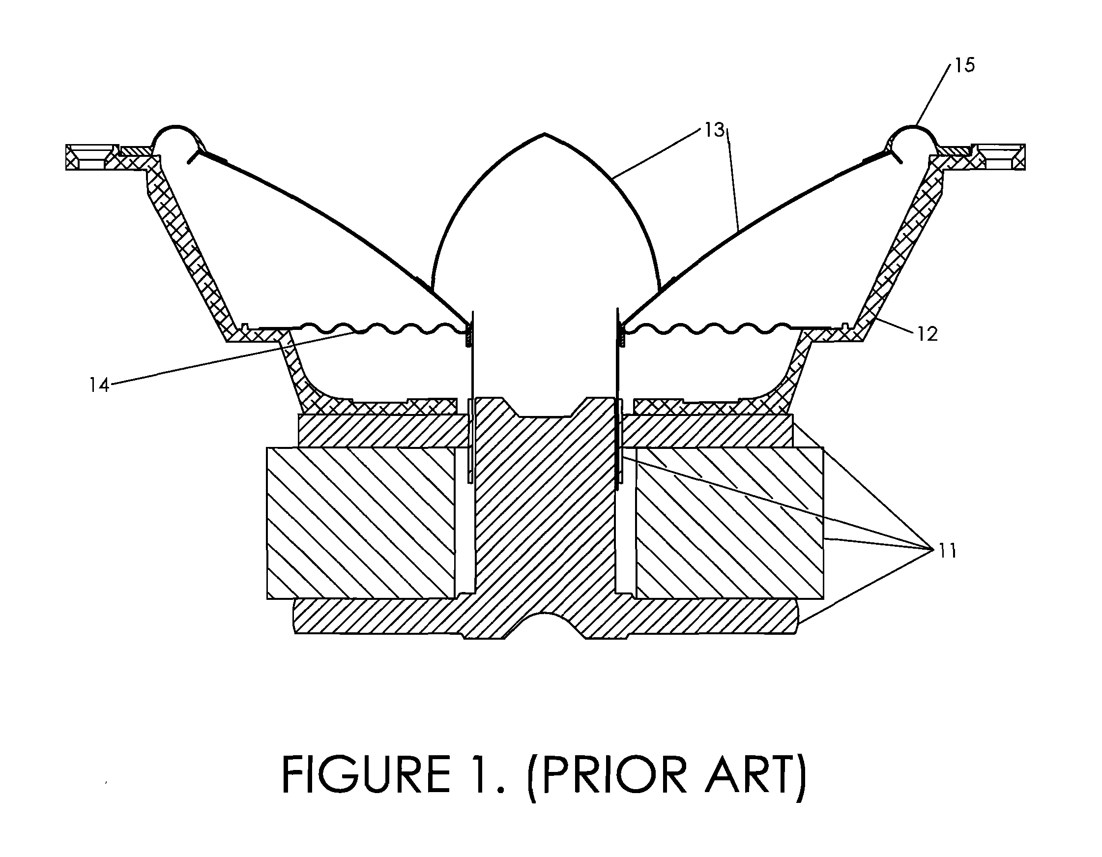
[0038]Referring first to FIG. 1, labelled PRIOR ART, a typical electro-dynamic loudspeaker driver comprises a magnetic motor system 11, frame 12 (sometimes called a “basket”), an axially-movable diaphragm 13, centering element 14 (sometimes called a “spider”), and flexible surrounding roll suspension 15. The inner edge of the flexible roll suspension 15 is attached to the outermost edge of the axially movable diaphragm 14 and the outer edge of the roll suspension 15 is connected to the rim flange of the frame 12. Consequently, the width of the surrounding roll suspension 15 is limited to the annular gap between the edge of the diaphragm 14 and the flange of frame 12.

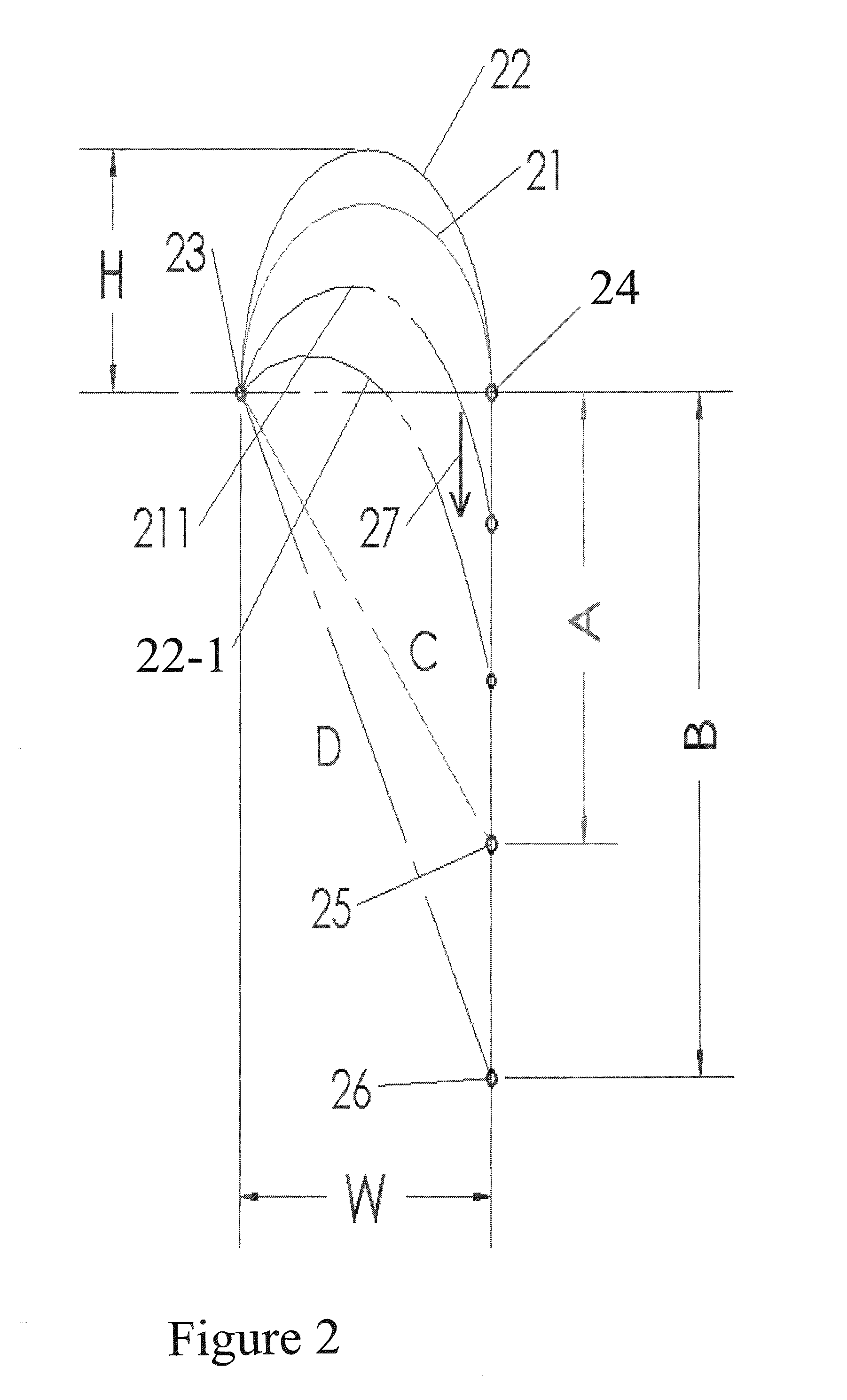
[0039]FIG. 2 illustrates schematically and in cross-section a semi-circular suspension roll profile 21 and a parabolic suspension roll profile 22, initially in the resting or neutral position. The frame attachment is represented by point 23 and the diaphragm attachment is represented by point 24, spaced apart by the widt...


PUM


Abstract

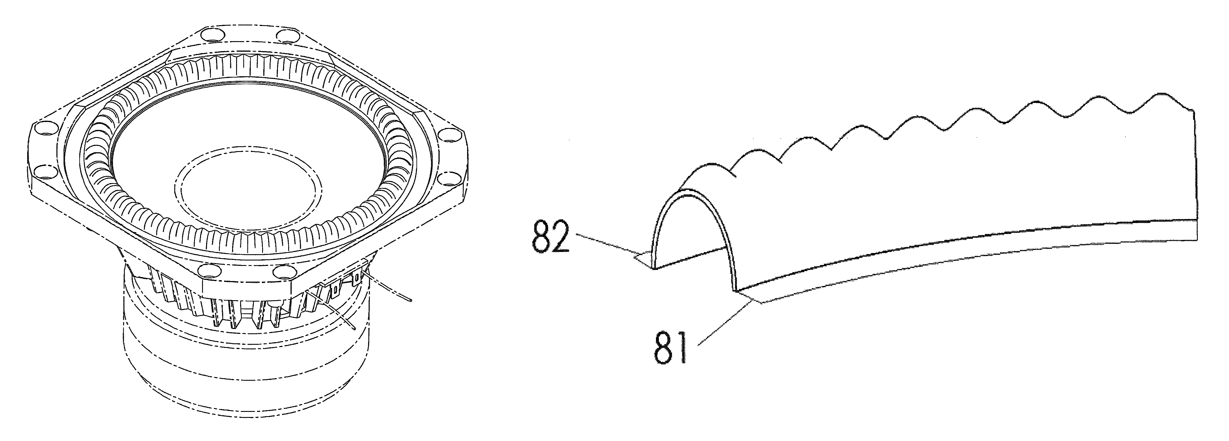
A loudspeaker driver has a diaphragm connected to a surrounding frame by a roll suspension which extends around the diaphragm and within the frame. The roll suspension connects the outer edge of the diaphragm to the inner edge of the frame and flexes as the diaphragm is displaced to and fro axially relative to the frame. In order to provide for better integrity of the roll suspension during its displacement, and reduce unwanted deformation and concomitant distortion, the suspension roll is provided with pleats extending across the roll suspension transversely to the direction of axial movement of the diaphragm to create a series of undulations (peaks and troughs) around the perimeter of the roll suspension. In transverse cross-section, the roll suspension is parabolic. The roll suspension varies continuously between each peak and adjacent trough. Preferably, outer surfaces of each peak and adjacent trough merge to a common point on the outer edge of the roll, while their inner surfaces merge to a common point on the outer edge of the roll, such that the peaks and troughs effectively disappear.

Description

TECHNICAL FIELD[0001]This invention relates to loudspeaker drivers and to suspensions therefore. The invention relates especially to drivers having a diaphragm suspended within a frame or so-called basket by a surrounding suspension which flexes as the diaphragm is driven back and forth relative to the frame by the loudspeaker drive unit, usually a voice coil. The invention also relates to a method of producing such a loudspeaker driver suspension.BACKGROUND[0002]The mechanical structure and function of loudspeaker drivers of the kind which have an electro-acoustic transducer are well known. A flexible surrounding suspension connects the periphery of the diaphragm to the surrounding frame. A second, smaller flexible suspension element connects the centre portion of the diaphragm to the frame; both suspension elements permit a drive unit, usually a “voice coil”, to move the diaphragm axially in order to radiate sound waves. Ideally, diaphragm motion is directly proportional to the el...

Claims


Application Information

Patent Timeline
Patent Type & Authority Patents(United States)
IPC IPC(8): H04R25/00
CPCH04R7/20H04R9/06H04R2307/207
Inventor BOGDANOV, OLEGSTITT, KEVIN ALEXANDER
Owner PARADIGM ELECTRONICS
Learn More