Controller of mobile robot

a robot control and mobile technology, applied in the field of mobile robot controllers, can solve the problems of inconvenient use, inconvenient transportation, and inability to move the cart w along the desired route, and achieve the effect of widening the pathway

Active Publication Date: 2012-12-25
HONDA MOTOR CO LTD
View PDF11 Cites 11 Cited by
  • Summary
  • Abstract
  • Description
  • Claims
  • Application Information

AI Technical Summary

Benefits of technology

[0016]The first aspect of the invention makes it possible to variably set the desired value of the angular difference about the yaw axis between the reference direction of an object and the direction of the moving velocity vector of the representative point of the object defined by the desired position trajectory (in other words, the tangential direction of a desired spatial route of the representative point of the object defined by the desired position trajectory) according to a required condition of the movement mode of the object. With this arrangement, the desired posture of the object about the yaw axis can be set to a posture satisfying a required condition of the movement mode of the object. Further, the motions of the mobile robot are controlled such that the position of the representative point of the object and the posture of the object follow the desired position trajectory and the desired posture trajectory which includes the desired value of the angular difference. This allows the object to be moved at a posture which satisfies the required condition of the movement mode.
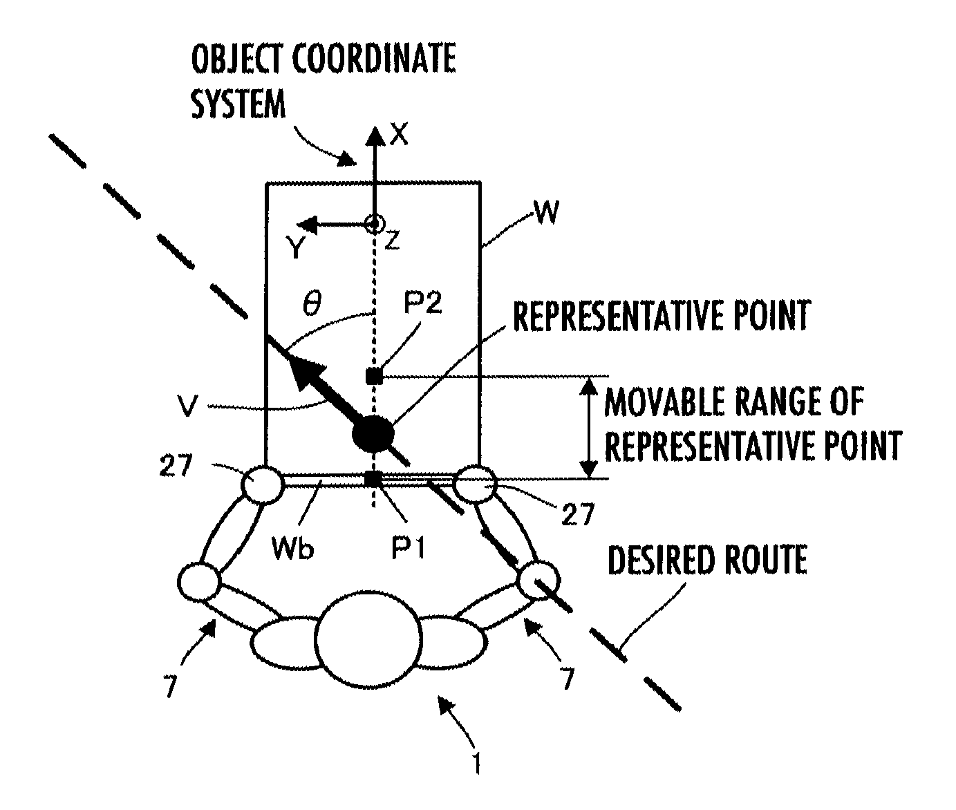
[0018]More specifically, depending on the angular difference, the posture of the object about the yaw axis easily deviates from a desired posture due to a moment attributable to a force acting on the object from the mobile robot. In such a circumstance, adjusting the position of the representative point of the object (the position in the object coordinate system) makes it possible to reduce the inertial moment of the object about the yaw axis passing the representative point. Thus, reducing the inertial moment of the object allows the posture to quickly follow the desired posture while controlling the force required to be applied to the object from the mobile robot in order to make the posture of the object follow the desired posture to a relatively small force (i.e., while restraining the force from becoming excessive).
[0020]In the third aspect of the invention, since the predetermined portion of the object in contact with the distal portion of the arm of the mobile robot is the portion adjacent to one end of the object, the posture of the object about the yaw axis tends to deviate from the desired posture more easily when the object is moved by the mobile robot as the desired value of the angular difference is closer to the second angular difference, i.e., as the direction of the interval between one end and the other end of the object and the direction of the moving velocity vector become closer to an orthogonal state. Therefore, according to the third aspect of the invention, the position of the representative point is set such that the inertial moment of the object is reduced as the desired value of the angular difference is closer to the second angular difference than the first angular difference. This arrangement allows the posture to promptly follow the desired posture while controlling the force required to be applied to the object from the mobile robot in order to make the posture of the object follow the desired posture to a relatively small force (i.e., while restraining the force from becoming excessive) in the aforesaid situation wherein the desired value of the angular difference is closer to the second angular difference, causing the posture of the object about the yaw axis to easily deviate from the desired posture. Further, in the situation wherein the desired value of the angular difference is closer to the first angular difference, the inertial moment of the object becomes slightly large, permitting higher stability of the posture of the object about the yaw axis.
[0022]According to the fourth invention, the desired value of the angular difference is set such that the lengthwise direction of the object remains in parallel to the wall or the side surface of the installed object at least from the point at which the distance from the wall or the side surface of the installed object to the object reaches a predetermined distance or less to the destination. This arrangement makes it possible to bring the object close to the wall or the installed object such that the posture of the object at the destination will be the desired posture, namely, the desired posture in which the lengthwise direction of the object is parallel to the wall or the side surface of the installed object, by moving the object to the destination along a monotonous route without the need for changing the posture of the object at a location in the vicinity of the destination.
[0025]According to the fifth aspect of the invention, even in the case where an obstacle exists beside the desired route, making the width of the pathway through which the object and the mobile robot pass is relatively small, it is possible to move the object and the mobile robot through the pathway by setting the desired posture of the object which allows the object or the mobile robot to avoid colliding with the obstacle.

Problems solved by technology

Therefore, it is actually impossible to move the cart W along the desired route 200.
As a result, it has inconveniently been taking time to make the position and the posture of the representative point of the cart W reach a final desired position and a final desired posture and it has also been inconveniently required to prepare a complicated desired position trajectory of the representative point of the cart W.
Furthermore, there has been another inconvenience described below with a conventional technique in which a desired posture trajectory of an object is generated such that the predetermined reference direction of the object is always the same direction as the moving velocity vector of the representative point defined by the desired position trajectory of the representative point of the object.

Method used


Image

  • Controller of mobile robot
  • Controller of mobile robot
  • Controller of mobile robot

Examples


Embodiment Construction

[0034]An embodiment of the present invention will be described with reference to FIG. 1 to FIG. 6. FIG. 1 is an external perspective view of a mobile robot according to the present embodiment and an object, FIG. 2 is a block diagram illustrating the system construction related to the motion control of the mobile robot in the present embodiment, FIG. 3 is a plan view of the mobile robot and the object moved by the mobile robot observed in the direction of a yaw axis, FIG. 4 and FIG. 5 are explanatory diagrams illustrating an example of the processing by a server provided in the system of the present embodiment, and FIG. 6 is a flowchart illustrating the processing by a controller provided in the mobile robot of the present embodiment.

[0035]Referring to FIG. 1, a mobile robot 1 according to the present embodiment is a bipedal mobile robot (humanoid robot). The bipedal mobile robot 1 has a body 3 serving as the basic body thereof, a pair of right and left legs 5, 5 extending from the b...


PUM


Abstract

A controller of a mobile robot that moves an object such that the position of a representative point of the object and the posture of the object follow a desired position and posture trajectory is provided. The desired posture trajectory of the object includes the desired value of the angular difference about a yaw axis between a reference direction, which is a direction orthogonal to the yaw axis of the object, and the direction of the moving velocity vector of the representative point of the object, defined by the desired position trajectory. The controller has a desired angular difference setting means which variably sets the desired value of the angular difference according to at least a required condition related to a movement mode of the object. This allows the object to be moved at a posture which meets the required condition of the movement mode.

Description

BACKGROUND OF THE INVENTION[0001]1. Field of the Invention[0002]The present invention relates to a controller of a mobile robot which performs an operation of holding an object, such as a cart, with the hands at the distal portions of the arms thereof, and moving the object such that the position and the posture of the object follow desired trajectories.[0003]2. Description of the Related Art[0004]A technique for having a mobile robot perform an operation of moving an object, such as a cart, with the distal portions of the arms of the mobile robot kept in contact with predetermined portions at one end of the object has been proposed by the present applicant as disclosed in, for example, Japanese Patent Application Laid-Open No. 2007-160428 (hereinafter referred to as patent document 1). According to the technique, the motions of a bipedal mobile robot as the mobile robot are controlled such that the position of a representative point of the object and the posture of the object follo...

Claims


Application Information

Patent Timeline
Patent Type & Authority Patents(United States)
IPC IPC(8): B25J9/10G05B19/04B25J5/00B62D57/032
CPCG05D1/0246G05D1/027G05D1/0274G06T7/20G05D2201/0211G05D2201/0217G06T2207/10016G06T2207/30252
Inventor OHNO, NOBUYUKIHASEGAWA, TADAAKI
Owner HONDA MOTOR CO LTD
Why Eureka
Try Eureka