
Cheek support apparatus

a technology for supporting devices and cheeks, which is applied in the field of cheek support devices, can solve the problems of poor gripping contact between the cheek piece and the stock of the rifle, user missing a target,

Inactive Publication Date: 2013-01-01
CRISWELL CURTIS DANIEL
View PDF12 Cites 10 Cited by
  • Summary
  • Abstract
  • Description
  • Claims
  • Application Information

AI Technical Summary

Benefits of technology

The apparatus provides stable cheek support during firing, allows for easy cleaning, and reduces wear on the rifle stock, enhancing usability and accuracy by ensuring a consistent cheek position without compromising the rifle's mechanical operation.

Problems solved by technology

These modes of attachment have inherent drawbacks, for example, poor gripping contact between the cheek piece and the stock of the rifle, loosening out of the cheek piece from the stock of the rifle, etc., during firing due to vibrations and other factors.
The loosening out of the cheek piece from the stock during firing distracts the user, which results in the user missing a target.
The loosening out of the cheek piece from the stock interferes with the rifle's mechanical operation.
Moreover, the stock may need to be modified for attaching conventional cheek pieces, which reduces the value of the rifle.
The need to accommodate the cleaning rod limits the height of the rifle's comb.
If the comb is too high, the cleaning rod cannot be inserted into the breech end of the barrel.
Furthermore, loading and unloading of a conventional cheek piece on the rifle's stock is time consuming, which proves to be a major drawback in times of emergencies.
Frequent installation and removal of the conventional cheek piece leads to deterioration in the surface finish of the rifle's stock, which further reduces the value of the rifle.
Hence, there is a long felt but unresolved need for a portable, easily installable and uninstallable cheek support apparatus that grips the stock of any firearm firmly, and that can be adjustably positioned to meet height requirements during cleaning and firing of the firearm.

Method used


Image

  • Cheek support apparatus
  • Cheek support apparatus
  • Cheek support apparatus

Examples


Embodiment Construction

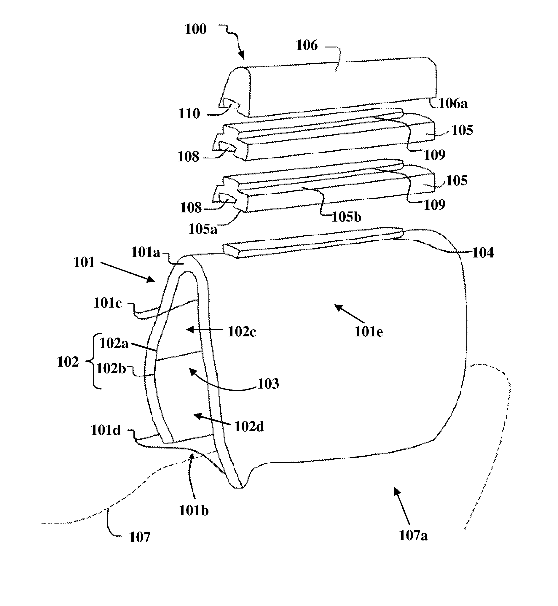
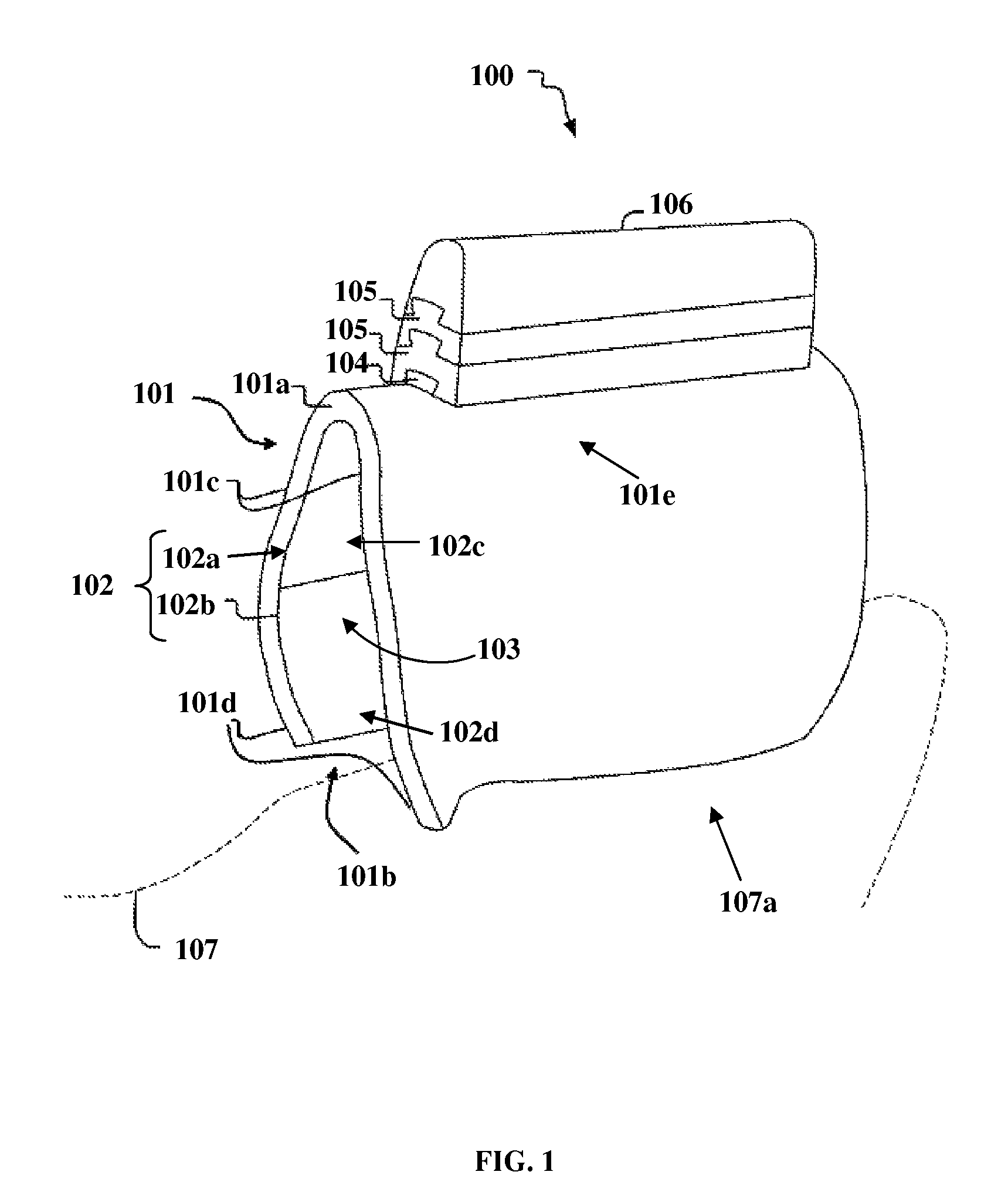
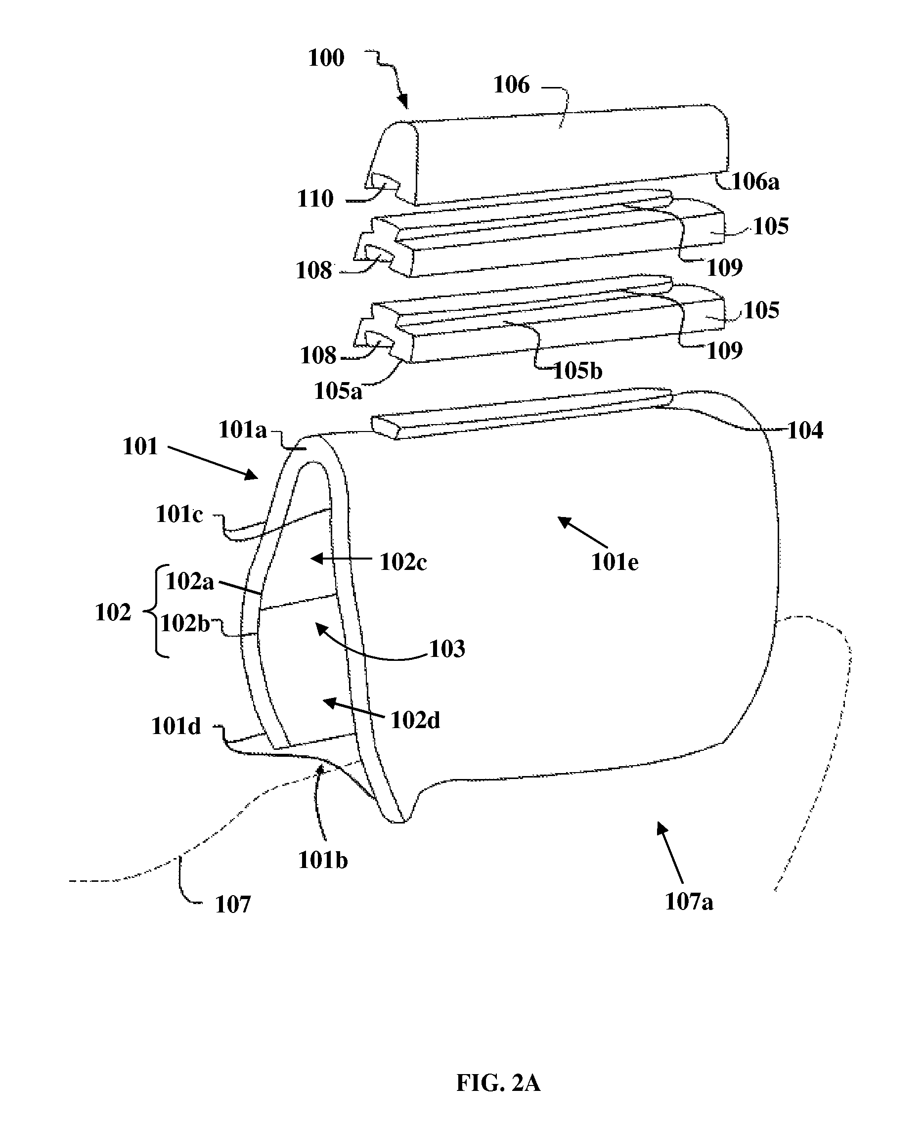
[0023]FIG. 1 exemplarily illustrates a perspective view of a cheek support apparatus 100 for a firearm 107. As exemplarily illustrated in FIG. 1, the cheek support apparatus 100 disclosed herein comprises a generally inverted U-shaped shell member 101 having a closed upper end 101a and an open lower end 101b, a base member 104, one or more shim members 105, and a cheek supporting member 106. The generally inverted U-shaped shell member 101 is herein referred to as a “shell member”. The shell member 101 is made of a form fitting material configured to conform to contours of a stock 107a of a firearm 107. As used herein, the term “firearm” refers to any device used for projecting one or more projectiles at a high velocity. The firearm 107 is, for example, a rifle, a shotgun, a carbine, a crossbow, etc. The form fitting material of the shell member 101 is a flexible and springy material, for example, a thermoplastic material manufactured by Kydex® LLC, etc. The shell member 101 is shap...


PUM

PropertyMeasurementUnit
coefficients of frictionaaaaaaaaaa
frictionaaaaaaaaaa
thermoplasticaaaaaaaaaa

Abstract

A cheek support apparatus comprising a generally inverted U-shaped shell member, a base member, and a cheek supporting member is provided for a firearm. The shell member made of a form fitting material, for example, a thermoplastic material, is selectively configured with different coefficients of friction to enable rigid contact of the shell member to a stock of the firearm. The shell member comprising an inner frictional surface defines an opening for accommodating the stock of the firearm. The base member is rigidly attached to a closed upper end of the shell member. In an embodiment, one or more shim members are removably attached on the base member for adjustably positioning the cheek supporting member on the base member. The cheek supporting member is removably attached on one or more of the shim members or the base member for supporting a user's cheek, for example, during recoil of the firearm.

Description

BACKGROUND[0001]A conventional cheek piece used in firearms today is attached to a stock of a rifle, for example, using adhesives, straps, laces, hook and loop fasteners, threaded fasteners such as screws, bolts, etc. These modes of attachment have inherent drawbacks, for example, poor gripping contact between the cheek piece and the stock of the rifle, loosening out of the cheek piece from the stock of the rifle, etc., during firing due to vibrations and other factors. The loosening out of the cheek piece from the stock during firing distracts the user, which results in the user missing a target. The loosening out of the cheek piece from the stock interferes with the rifle's mechanical operation. Moreover, the stock may need to be modified for attaching conventional cheek pieces, which reduces the value of the rifle.[0002]In order to shoot accurately, a user must hold the rifle the same way every time and therefore needs to hold the user's eye at a particular height that allows the...

Claims


Application Information

Patent Timeline
Patent Type & Authority Patents(United States)
IPC IPC(8): F41C23/14
CPCF41C23/14Y10T29/49826
Inventor CRISWELL, CURTIS DANIEL
Owner CRISWELL CURTIS DANIEL
Learn More